Negative refractive index materials and methods for making same
a technology of refractive index and materials, applied in the field of negative refractive index materials and methods for making same, can solve the problems of loss of resolution and large optical loss of materials
- Summary
- Abstract
- Description
- Claims
- Application Information
AI Technical Summary
Benefits of technology
Problems solved by technology
Method used
Image
Examples
example 1
Pure MgB2
[0094]HIP on MgB2 powders was performed in a custom fabricate niobium HIP container having green (i.e., before compression) dimensions of approximately one cubic inch. The ‘cans’ were fabricated using an Exo TIG inert atmosphere glove box welder facility to get clean ductile welds that survive the demands of high temperature HIP. The can was filled with MgB2 powder (Alfa Aesar) and fully off-gassed with a vacuum to remove adsorbed species on the powder surfaces. The integrity of the filled can was checked with a residual gas analyzer and helium leak detector connected to the pump-off tube, after which it was sealed. The sealed can was placed in a HIP unit and treated at 600° C.
[0095]The completed MgB2 billet is shown in FIG. 11. The MgB2 billet is very hard and robust with a measured density is 2.63 g / cm3, which is close to the theoretical value. It can be cut with a low-speed diamond blade, and samples of about 1 mm were removed for ellipsometric, no...
example 2
MgB2 / SiC Metamaterials
[0096]MgB2 (Alfa Aesar) and 30 vol % SiC nominally, 130 nm powder (Nanostructured and Amorphous Materials) or 0.5 μm BF-17 powder (H. C. Starck) were mixed and milled in a ball mill using zirconia beads. The BF-17 powder was first suspended in THF, and the first fraction was removed after 10 minutes for use in the composite. For milling, zirconia beads were used because they are harder than MgB2, but it is not as hard as SiC. Milling for 80 hours produced powders that were no bigger than a half micron in size, and which were very well distributed.
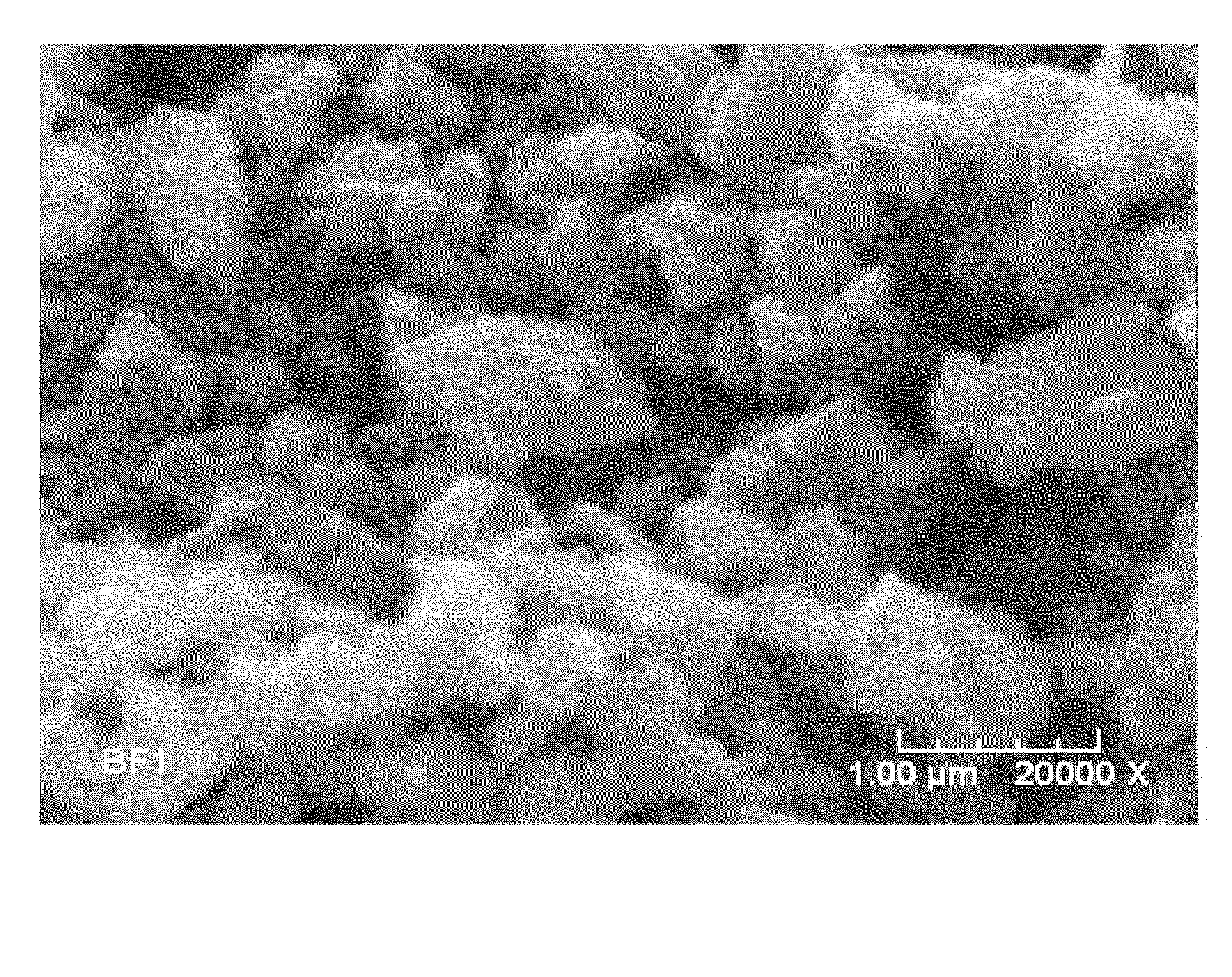
[0097]These materials were then encapsulated in a metal can and HIPped at a temperature of 700° C. to ensure that the MgB2 consolidated well, but remained well below the sintering temperature of SiC. A thin slice, about 1 mm, was cut from the resulting billets with a diamond blade, and polished with diamond grit as before. SEM images of the polished cross section of the BF-17 composite are shown i...
example 3
E-Beam Sintering
[0098]Electron beam (e-beam) sintering of composites of MgB2 / SiC was accomplished using a technique that delivers small (1 cm2 to large 30×30 cm) sintering to ultra thin (200 nm) to thicknesses of 6.5 microns in ambient conditions. Samples for e-beam sintering were made by milling the nominally 130 nm SiC particles with 325 mesh (about 45 μm) MgB2 powder for 80 h in a dry ball mill. The volume fraction (assuming full density) was 30% SiC. Zirconia beads were used for the milling, which are harder than MgB2 but not as hard as SiC, which were effective in breaking down the boride particles.
[0099]To make films, 0.05 g of the powder was mixed with 5 g of acetone in a test tube, and shaken. The fast-settling particles were removed after 30 minutes, and the remaining supernatant, in which the particles were settled out more slowly, was used to cast the films. Silicon chips were placed in 4 mL (a depth of about ⅜″) of the remaining suspension and the acetone allowed to slow...
PUM
| Property | Measurement | Unit |
|---|---|---|
| Temperature | aaaaa | aaaaa |
| Temperature | aaaaa | aaaaa |
| Temperature | aaaaa | aaaaa |
Abstract
Description
Claims
Application Information
 - R&D
- Intellectual Property
- Life Sciences
- Materials
- Tech Scout
- Unparalleled Data Quality
- Higher Quality Content
- 60% Fewer Hallucinations
Browse by: Latest US Patents, China's latest patents, Technical Efficacy Thesaurus, Application Domain, Technology Topic, Popular Technical Reports.
© 2025 PatSnap. All rights reserved.Legal|Privacy policy|Modern Slavery Act Transparency Statement|Sitemap|About US| Contact US: help@patsnap.com


