
Solid electrolytic capacitor

a technology of electrolytic capacitors and solids, applied in the direction of fixed capacitor details, variable capacitors, fixed capacitors, etc., to achieve the effect of significant heat resistance and low esr

Inactive Publication Date: 2010-06-24
SANYO ELECTRIC CO LTD
View PDF5 Cites 37 Cited by
  • Summary
  • Abstract
  • Description
  • Claims
  • Application Information

AI Technical Summary

Benefits of technology

The present invention provides a solid electrolytic capacitor that includes a conductive matrix and carbon nanotube in a mixture layer to achieve low ESR, low LC, and high heat resistance. The carbon nanotube is dispersed in the conductive matrix and the mixture layer is deposited in a way that the conductive matrix particles adhere to the carbon nanotube or are dispersed throughout the conductive matrix. This results in a low ESR, low LC, and reliable solid electrolytic capacitor that can withstand high temperatures.

Problems solved by technology

However, a variety of factors prevent a solid electrolytic capacitor from having a conductive polymer layer deposited with a desired conductance, and studies are currently still underway.

Method used


Image

  • Solid electrolytic capacitor
  • Solid electrolytic capacitor

Examples


example 1

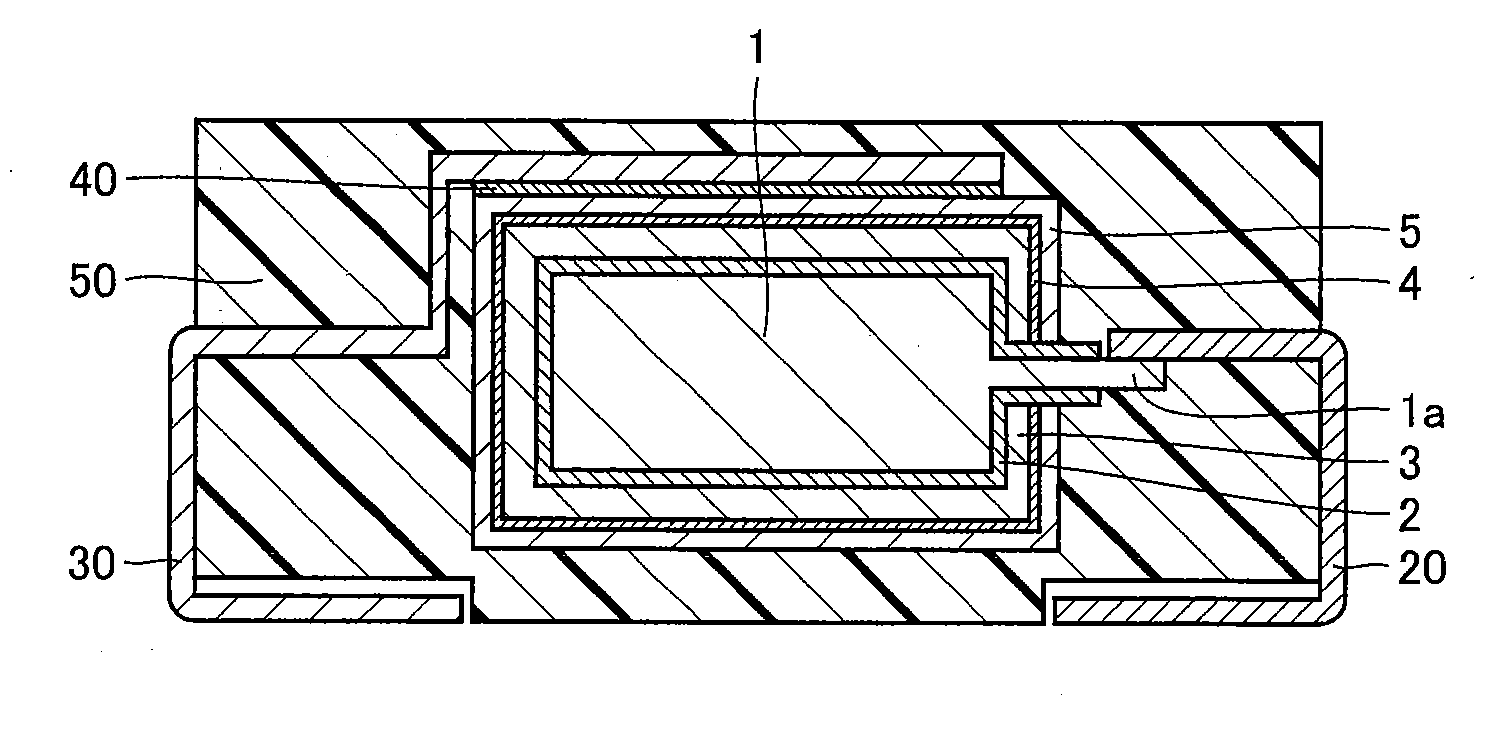
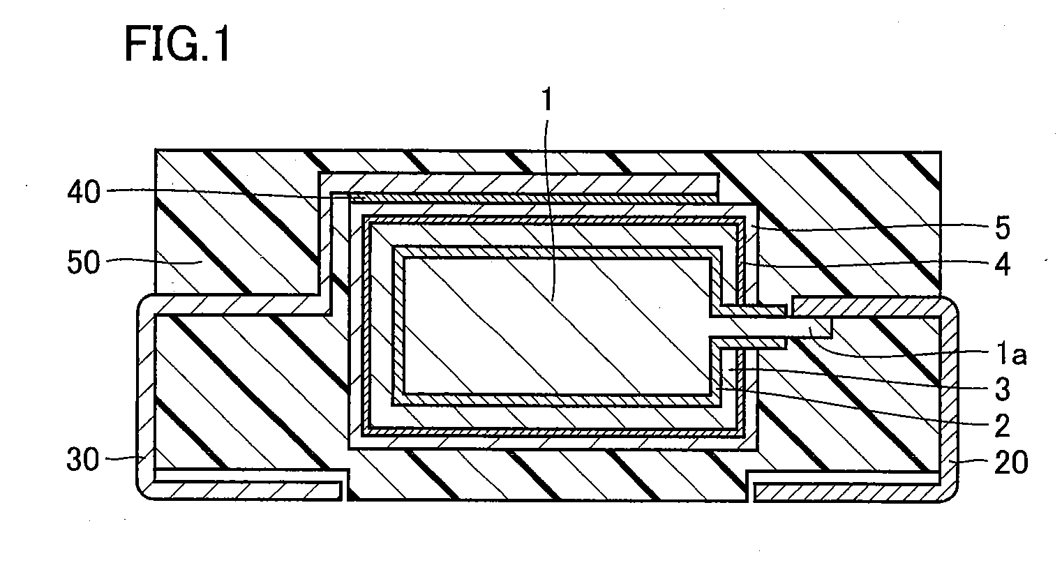
[0045]With reference to FIG. 1, an example 1 will be described. Anode portion 1a formed of tantalum is planted in a compact of powdery tantalum and vacuum-sintered to provide anode body 1 having anode portion 1a provided thereto. Then, a well known method is employed to subject the intermediate product to a chemical treatment or the like to prepare anode body 1 serving as an anode having a surface with dielectric coating film 2.

[0046]Then a polymerization solution containing pyrrole serving as a source material for conductive polymer layer 3, dopant and the like is prepared and employed in an electro-oxidative polymerization method to deposit conductive polymer layer 3 of 40 μm in thickness on dielectric coating film 2.

[0047]Then anode body 1 having dielectric coating film 2 with conductive polymer layer 3 deposited thereon is immersed in a liquid of mixture of a solution containing polyaniline serving as a conductive matrix and carbon nanotubes added thereto and dispersed therein. ...

example 2

[0049]A solid electrolytic capacitor is fabricated similarly as done in example 1, except that after mixture layer 4 is deposited a 3 μm thick carbon layer is further deposited.


PUM

PropertyMeasurementUnit
thicknessaaaaaaaaaa
thicknessaaaaaaaaaa
thicknessaaaaaaaaaa

Abstract

A solid electrolytic capacitor includes a capacitor element including: an anode body; a dielectric coating film deposited on a surface of the anode body; a conductive polymer layer deposited on the dielectric coating film; and a mixture layer deposited on the conductive polymer layer and containing a conductive matrix and carbon nanotubes, the anode body, the dielectric coating film, the conductive polymer layer and the mixture layer being deposited in sequence.

Description

BACKGROUND OF THE INVENTION[0001]1. Field of the Invention[0002]The present invention relates to solid electrolytic capacitors providing high performance.[0003]2. Description of the Related Art[0004]In recent years there has been a demand for a small size and large capacity capacitor for high frequency as electronic equipment is reduced in size and weight. As one such capacitor there has been proposed a solid electrolytic capacitor employing a conductive polymer compound to form a solid electrolyte layer.[0005]A solid electrolytic capacitor may have a basic configuration including an anode body formed of a sintered compact of tantalum, niobium, titanium, aluminum or similar valve metal, a dielectric coating film formed of an oxidized surface of the anode body, a solid electrolyte layer formed of a conductive polymer layer deposited on the dielectric coating film, a carbon layer, and a cathode body. The cathode body may be a silver paste or similar metal paste layer.[0006]The above s...

Claims


Application Information

Patent Timeline
Patent Type & Authority Applications(United States)
IPC IPC(8): H01G9/15H01G9/025
CPCH01G9/15H01G9/0425
Inventor MIYACHI, YUJIGOTO, KOHEIMORITA, KOICHITAKAMATSU, TAKESHI
Owner SANYO ELECTRIC CO LTD
Learn More