
Zinc oxide film forming method and apparatus

a zinc oxide film and forming method technology, applied in the field of zinc oxide film forming method and apparatus, can solve the problems of low productivity of dye-sensitive solar cells in the document 1 technology, zinc oxide film falling off from the substrate, etc., and achieve the effect of superior adhesion to the conductive layer and easy and efficient formation of porous zinc oxide film

Inactive Publication Date: 2010-07-01
DAINIPPON SCREEN MTG CO LTD
View PDF5 Cites 12 Cited by
  • Summary
  • Abstract
  • Description
  • Claims
  • Application Information

AI Technical Summary

Benefits of technology

The present invention provides a method and apparatus for easily and efficiently forming a porous zinc oxide film on a base member, which can serve as a photoelectric conversion layer in a dye-sensitized solar cell. The method involves depositing a zinc oxide film onto a conductive layer on the base member and then applying a film forming material containing zinc oxide and solvent onto the deposit. The solvent is then removed to form the porous zinc oxide film. The method can be further enhanced by adding metal to the zinc oxide film or adding a wiring pattern to the conductive layer to facilitate the removal of a mask. The invention allows for the formation of a strong bond between the zinc oxide film and the conductive layer, resulting in a high-quality photoelectric conversion layer.

Problems solved by technology

However, there is a problem that productivity of the dye-sensitized solar cell in the technique of the Document 1 becomes low, because long process time is required for electrodeposition of the zinc oxide film and desorption of the template agent.
As the result, there is a case where the zinc oxide film falls off from the substrate in the downstream processes of manufacturing of dye-sensitized solar cell.

Method used


Image

  • Zinc oxide film forming method and apparatus
  • Zinc oxide film forming method and apparatus
  • Zinc oxide film forming method and apparatus

Examples


Embodiment Construction

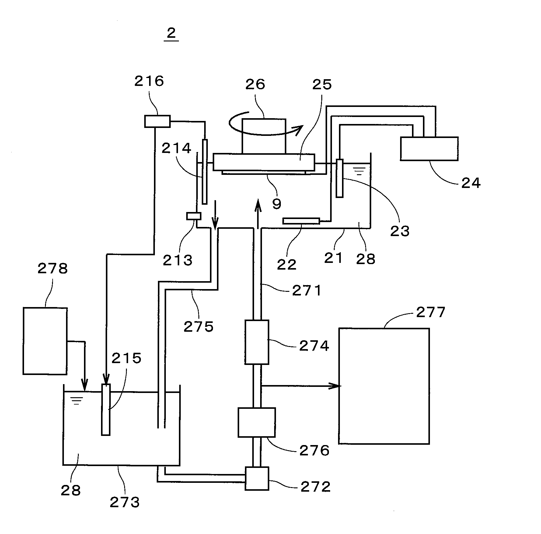
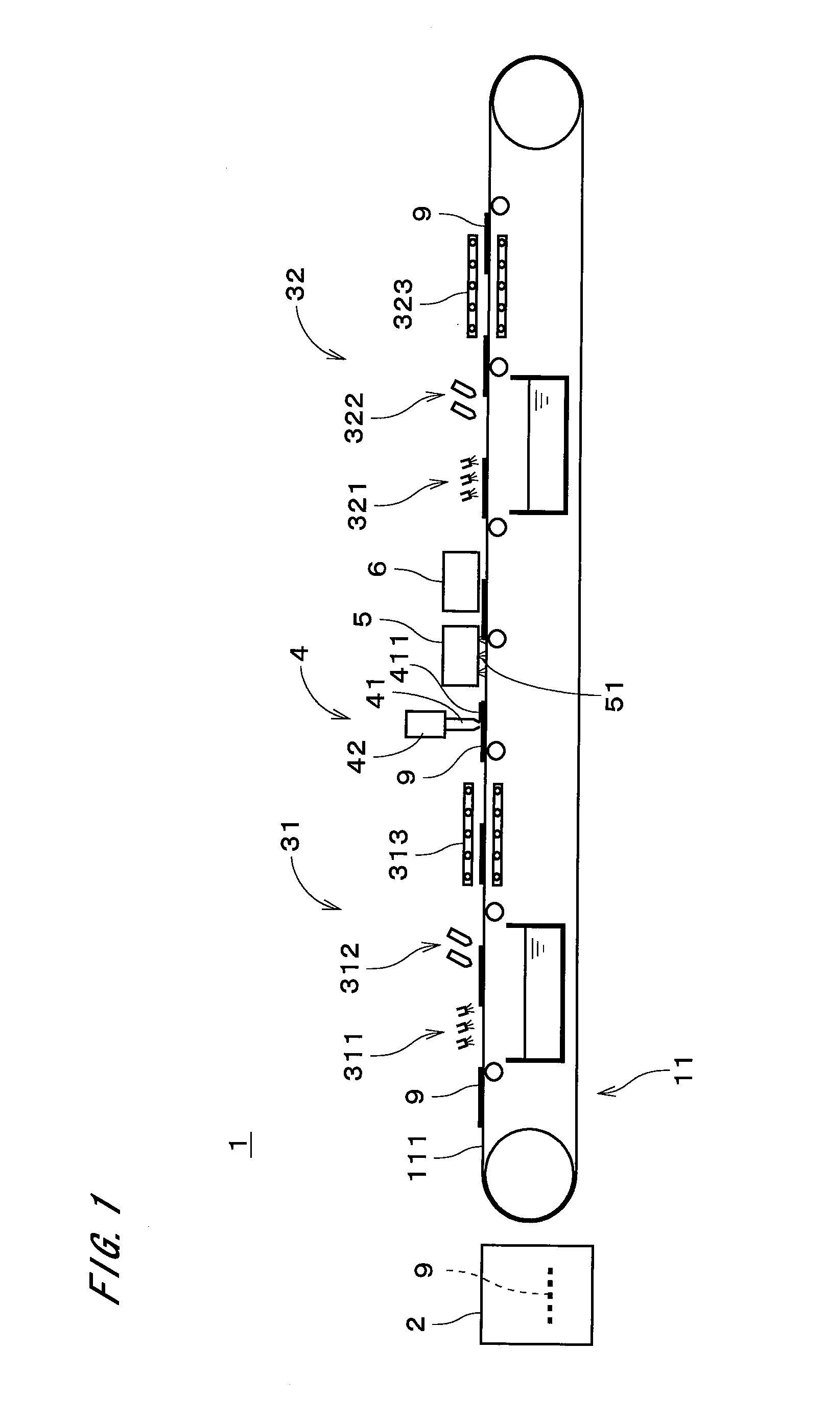
[0025]FIG. 1 is a view showing a constitution of a zinc oxide film forming apparatus 1 in accordance with a first preferred embodiment of the present invention. The zinc oxide film forming apparatus 1 is used for forming a porous thin film of zinc oxide on a transparent resin substrate 9 which has a transparent conductive layer such as ITO (Indium Tin Oxide) film or FTO (Fluorine-doped Tin Oxide) film. In the downstream processes, a counter substrate having a counter electrode (a counter electrode conductive layer) is provided so that the counter substrate faces the resin substrate 9 on which the zinc oxide film is formed, liquid electrolyte is injected between two substrate to form a charge transport layer (electrolyte layer), and therefore the dye-sensitized solar cell is manufactured. As above, the zinc oxide film formed in zinc oxide film forming apparatus 1 is used as a photoelectric conversion layer (it is also called as photoelectrode layer) in the dye-sensitized solar cell.

[...


PUM

PropertyMeasurementUnit
flow rateaaaaaaaaaa
temperatureaaaaaaaaaa
electrical potentialaaaaaaaaaa

Abstract

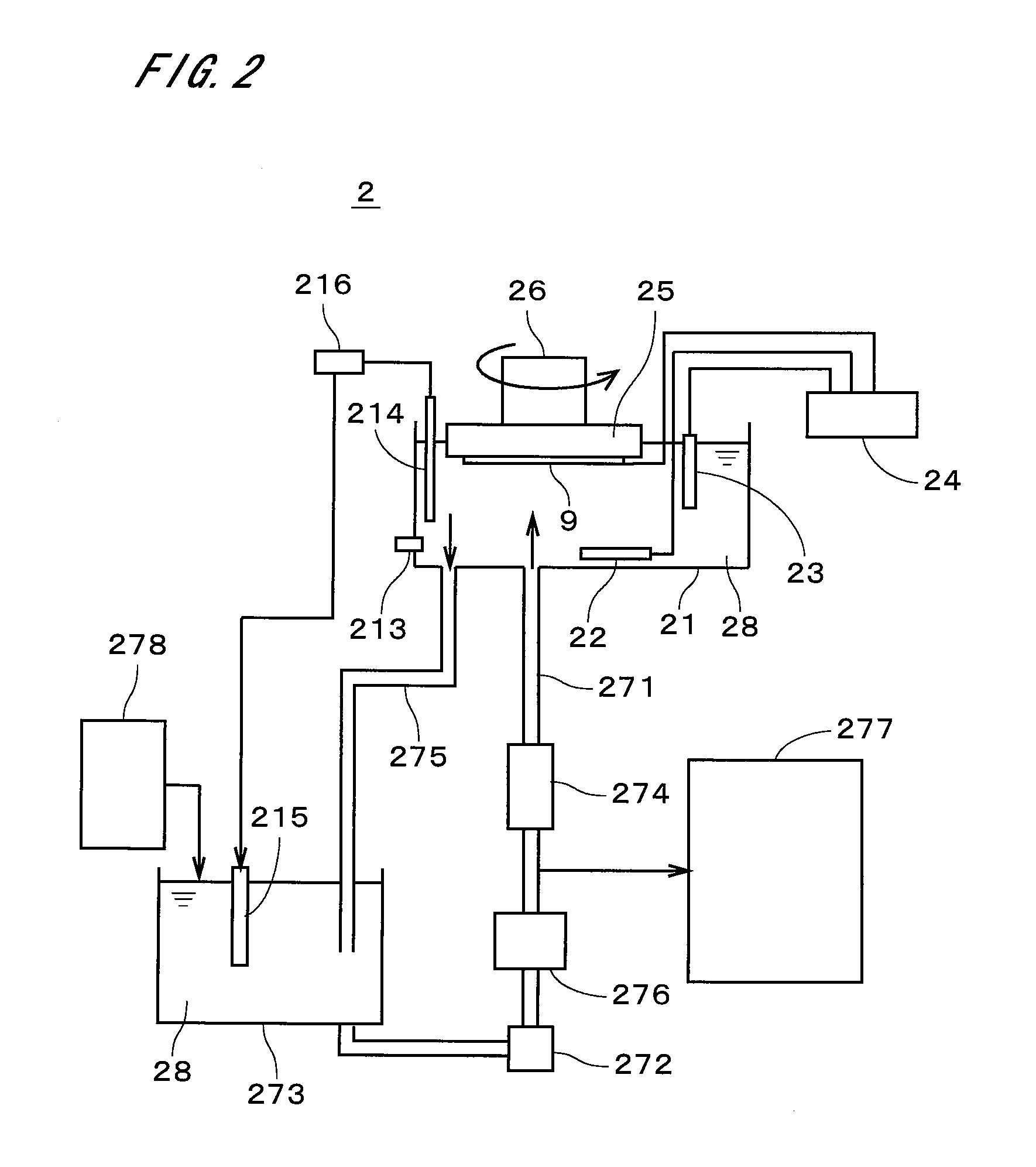
In the zinc oxide film forming apparatus (1), the deposit containing zinc oxide is formed on the conductive layer of the resin substrate (9) by electrodeposition in the deposition part (2), and the resin substrate (9) is carried to the applying part (4). Subsequently, the film forming material which is in liquid or paste form and contains particles of zinc oxide and solvent is applied onto the conductive layer, and then the solvent is removed from the film forming material on the conductive layer by volatilization. It is therefore possible to easily and efficiently form the porous zinc oxide film which has superior adhesion to the conductive layer of the resin substrate (9).

Description

TECHNICAL FIELD[0001]The present invention relates to a technique of forming a porous zinc oxide film on a base member, which is a film used as a photoelectric conversion layer in a dye-sensitized solar cell.BACKGROUND ART[0002]Recently, a dye-sensitized solar cell have been paid attention to and it can be used as a power source of a various product without impact to its design and be manufactured with low cost. The dye-sensitized solar cell has a structure where a transparent substrate having a conductive layer (for instance, a layer of ITO (Indium Tin Oxide) film or FTO (Fluorine-doped Tin Oxide) film), a photoelectric conversion layer, a charge transport layer, and a counter substrate having a counter electrode conductive layer are build up. The technique where paste containing semiconductive particles such as titanium oxide is applied on the substrate and the paste is burned at a high temperature, is employed as a technique of forming a porous semiconductive layer which becomes ...

Claims


Application Information

Patent Timeline
Patent Type & Authority Applications(United States)
IPC IPC(8): H01L31/18C23C14/00
CPCC23C18/1262C23C18/54C25D3/22H01G9/204H01G9/2059Y02E10/542
Inventor YANE, TAKESHI
Owner DAINIPPON SCREEN MTG CO LTD
Learn More