Carriage for Automating Welding, Brazing, Cutting and Surface Treatment Processes

a technology for automating welding and brazing, applied in the direction of soldering media, workpiece edge portions, auxilary devices for soldering, etc., can solve the problems of inability to follow small local deviations in the joint trajectory, stiff rails, and time-consuming to lay out the rails arranged,

Inactive Publication Date: 2010-07-15
FORCE TECH
View PDF7 Cites 55 Cited by
  • Summary
  • Abstract
  • Description
  • Claims
  • Application Information

AI Technical Summary

Benefits of technology

[0010]It is an object of the invention to provide a welding carriage comprising surface adaptive means. This object is achieved, when the welding carriage mentioned in the opening paragraph is characterized in that at least one of the wheels of the welding carriage are arranged to be flexed to assume more than one angle compared to a bottom side and/or top side of the welding carriage. For example, all four wheels of a welding carriage comprising four wheels may be arranged to be flexed to assume more than one angle compared to a bottom side and/or top side of the welding carriage. Hereby, at least one of the wheels of the welding carriage may be able to adapt to any surface e.g. a planar surface and/or a spherical surface and/or a cylindrical surface etc. Further, the left set of wheels and/or the right set of wheel and/or each individual wheel can be bent e.g. inwards, i.e. towards the botto

Problems solved by technology

Furthermore, the rails are stiff and cannot follow small local deviations in the joint trajectory.
Further, it is time consuming to lay out the rails arranged for supporting the welding carriage.
However, there are some obvious disadvantages of these carriages.
For instance, the electricity can fail, for which reason the holding force of an electromagnet will vanish, while the holding force of a electromagnet as well as a permanent magnet varies and may drop critically when moving on very curved surfaces, e.g. inside a pipe if the diameter becomes too small.
A disadvantage of this carriage is that it uses a reflective tape for guidance that very precisely has to be attached or affixed to the subject that is to be welded upon.
Such subjects will normally be dirty and/or slightly corroded which further makes the attachment of the reflective

Method used


Image

  • Carriage for Automating Welding, Brazing, Cutting and Surface Treatment Processes
  • Carriage for Automating Welding, Brazing, Cutting and Surface Treatment Processes
  • Carriage for Automating Welding, Brazing, Cutting and Surface Treatment Processes

Examples


Embodiment Construction

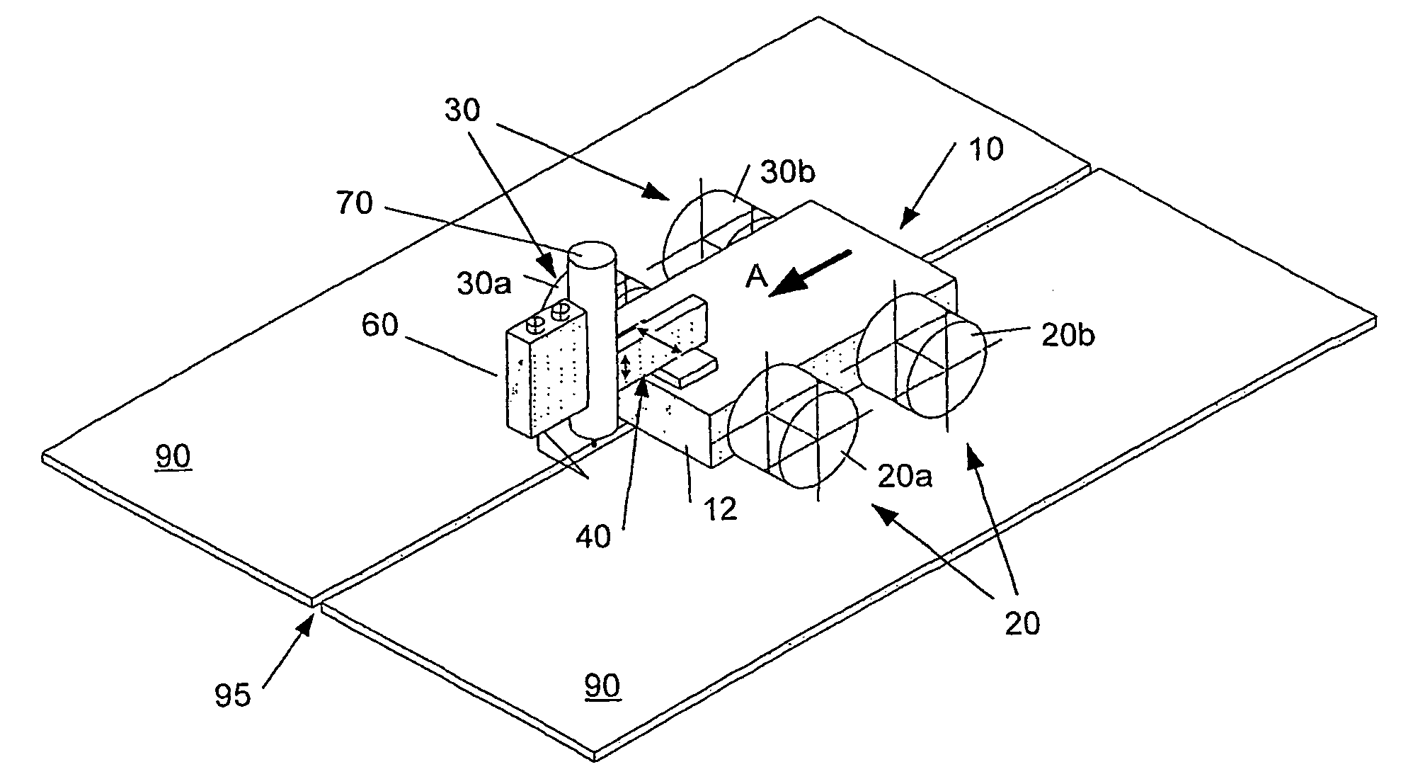
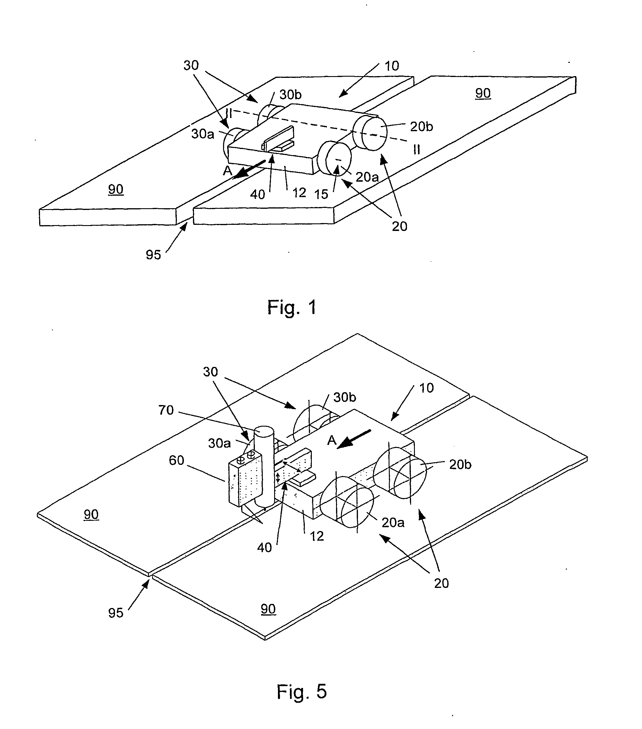
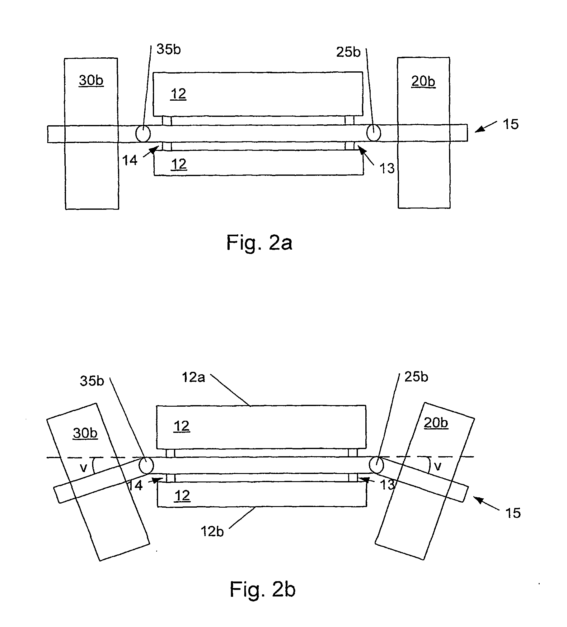
[0038]FIG. 1 is a schematic drawing of a welding carriage 10 according to an embodiment of the invention. The welding carriage 10 is placed upon a work piece 90 having a joint 95 which is to be welded. The welding carriage 10 has a direction of movement indicated by the arrow A. The welding carriage 10 has a body / chassis 12 and two sets of wheels 20, 30, whereof one set of wheels 20 is a left set of wheels 20a, 20b and the other set of wheels is a right set of wheels 30a, 30b, where the indications “left” and “right” correspond to the wheels on the left and right side, respectively, of the welding carriage when this is seen from above in such an orientation that the direction of movement is forward. Each wheel is pivotal around an axle 15 extending through the body 12 of the welding carriage 10 (also see FIGS. 2a and 2b). Also shown in FIG. 1 is adjustable means 40 for supporting a welding device, such as a welding torch and / or a cutting device and / or another device. When the weldin...


PUM

PropertyMeasurementUnit
Angleaaaaaaaaaa
Angleaaaaaaaaaa
Angleaaaaaaaaaa

Abstract

This invention relates to a welding carriage operable to drive across a surface of a work piece having a joint to be welded. The welding carriage comprises a number of wheels, where each wheel is pivotal around an axle and where each wheel is a magnetic wheel; the welding carriage further comprises means for supporting a welding device wherein at least one of the wheels can be flexed inwardly or outwardly so that the welding carriage can travel over curved surfaces. The welding carriage can travel over magnetizable surfaces having any direction, e.g. orientation in space. The welding carriage can carry a laser sensor arrangement arranged to detect the position as well as the direction of a joint to be welded, so that the welding carriage is applicable for performing fully automated welding.

Description

FIELD OF THE INVENTION[0001]The invention relates to a carriage for automating welding, brazing, cutting, surface treatment processes, etc. where the carriage comprises a number of wheels, where each wheel is pivotal around an axle and where each wheel is a magnetic wheel, wherein the welding carriage further comprises means for supporting e.g. a welding device. The invention moreover relates to methods for operating such a carriage.BACKGROUND OF THE INVENTION[0002]Welding automation using a carriage for transporting a welding device, such as a welding torch, e.g. along a joint between two surfaces to be welded is well known in literature and accepted in the industry as a feasible tool for decreasing the involvement of a skilled human welder.[0003]Several commercially available systems are known. For instance, Bug-O Systems, Gullco and ESAB produce rail-based systems where portable rails using permanent magnets are mounted to the welded structure for carrying and guiding a carriage ...

Claims


Application Information

Patent Timeline
IPC IPC(8): B23K9/00
CPCB23K37/0264B23K37/0252B23K37/02B23K37/00
Inventor CHRISTENSEN, KIM HARDAMLARSEN, ULFSORENSEN, HENRIK
Owner FORCE TECH
Why Eureka
Try Eureka