Internal combustion engine

a combustion engine and combustion chamber technology, applied in the field of gas preparation, can solve the problems of increased installation space, increased maintenance costs, and impaired high-activity chemical activity, and achieve the effect of facilitating resource conservation, safe use and efficient us

Inactive Publication Date: 2010-07-22
MAGINEERING INC
View PDF14 Cites 17 Cited by
  • Summary
  • Abstract
  • Description
  • Claims
  • Application Information

AI Technical Summary

Benefits of technology

[0028]Large amounts of water are included in the exhaust gas introduced during intake in exhaust gas recirculation. This water is used to produce OH radicals that can contribute to combustion. In other words, combustion can be efficiently performed in this internal-combustion engine by using plasma to reform oxidizing agents.
[0029]In other words, there can be provided an internal-combustion engine that allows plasma to be used safely, efficiently, and in a manner conducive to resource conservation.

Problems solved by technology

In the internal-combustion engine disclosed in Patent Document 1, the fuel-reforming chamber must be provided separately, and problems are presented in that the installation space is enlarged.
Storing fuel that has been reformed and made more combustible also presents safety problems.
Additionally, a long period time passes before the reformed fuel is actually combusted, and the high chemical activity that was conferred may be impaired.
The mesh electrode also impedes the flow channel for exhaust gas recirculation, and the efficiency of supplying exhaust gas is impaired.

Method used


Image

  • Internal combustion engine
  • Internal combustion engine
  • Internal combustion engine

Examples


first embodiment

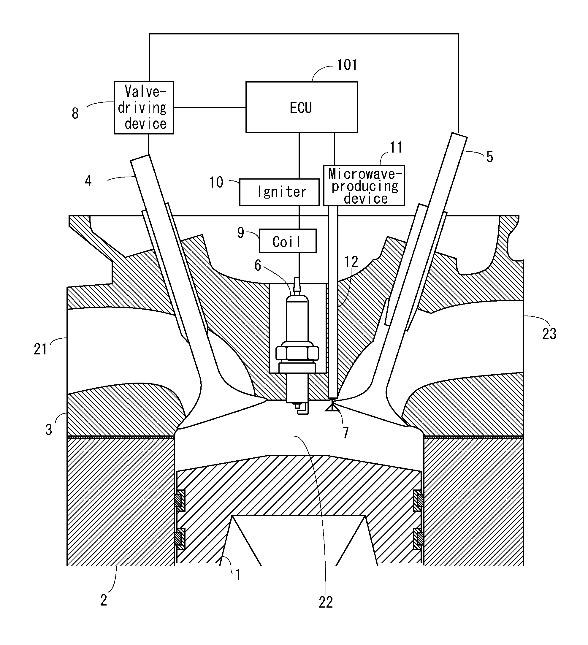
[0035]FIG. 1 is a cross-sectional view that shows the configuration of an internal-combustion engine according to a first embodiment of the present invention.

[0036]The internal-combustion engine according to the first embodiment of the present invention has a combustion chamber 22 that is configured from a piston 1, a cylinder liner 2, and an engine head 3, as shown in FIG. 1.

[0037]A spark plug 6 for igniting the fuel mixture and an antenna 7 for generating plasma in the fuel mixture or in the burnt gas within the combustion chamber 22 are also provided to the combustion chamber 22.

[0038]In the combustion chamber 22, an intake valve 4 opens, whereby fresh gas is taken in, and an exhaust valve 5 opens, whereby burnt gas is discharged. The intake valve 4 and the exhaust valve 5 are opened and closed by a valve-driving device 8.

[0039]A constant spatial volume is maintained in the combustion chamber 22 even when the piston 1 is at top dead center, and therefore a portion of the burnt ga...

second embodiment

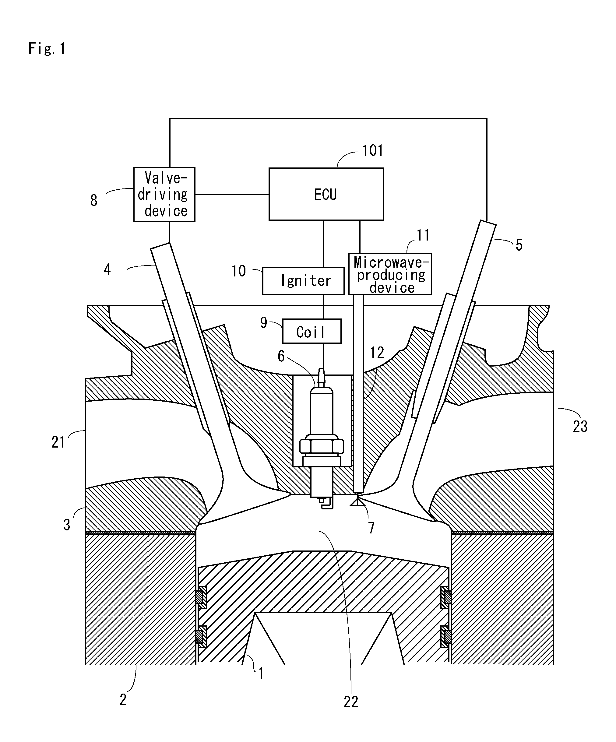
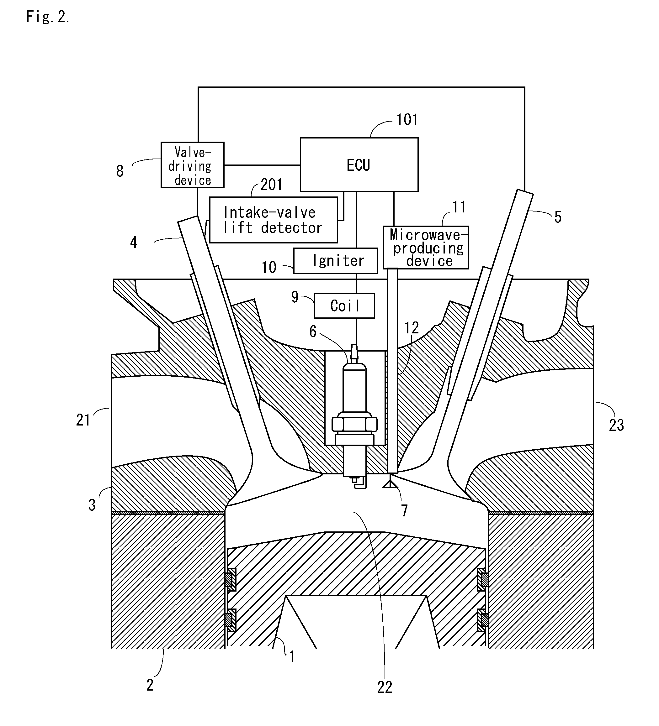
[0044]FIG. 2 is a cross-sectional view that shows the configuration of an internal-combustion engine according to a second embodiment of the present invention.

[0045]The internal-combustion engine according to the second embodiment of the present invention has an intake-valve lift detector 201, as shown in FIG. 2. The intake-valve lift detector 201 may be an eddy-current displacement gauge or a laser-Doppler displacement gauge. The intake-valve lift detector 201 detects the amount of lift (opening state) of the intake valve 4 and sends a detection signal to the control device (ECU) 101.

[0046]The antenna 7 generates microwaves timed after exhausting concludes and before intake begins, and activates the burnt gas remaining in the combustion chamber 22, a shown in FIG. 4.

[0047]The timing of the generation of microwaves is determined in the control device (ECU) 101 according to the output of the intake-valve lift detector 201. Control can thereby be prevented from deteriorating due to in...

third embodiment

[0048]FIG. 3 is a cross-sectional view that shows the configuration of an internal-combustion engine according to a third embodiment of the present invention.

[0049]The internal-combustion engine according to the third embodiment has an exhaust-gas recirculation mechanism, as shown in FIG. 3. This internal-combustion engine is such that so-called external exhaust gas recirculation; i.e., feeding back combustion exhaust gas toward an intake port 21, is used to reduce the combustion temperature. The combustion exhaust gas is fed back via an exhaust port 23 and through a conducting pipe 31 toward the intake port 21. The flow volume of the conducting pipe 31 is controlled by an on-off valve 32. The on-off valve 32 is controlled by the control device (ECU) 101.

[0050]The rest of the configurations are identical to the configuration of the first embodiment.

[0051]The concentration of burnt gas is high in this embodiment, and therefore plasma may also be generated even after intake commences....


PUM


Abstract

There is provided an internal-combustion engine that allows plasma to be used safely, efficiently, and in a manner conducive to resource conservation. An internal-combustion engine having an intake valve for opening and closing a combustion chamber, the internal-combustion engine comprising a valve-driving mechanism for driving the intake valve; and a plasma-generating device positioned within a region containing gas used for combustion during a combustion stroke, the plasma-generating device being composed of an antenna and a microwave-generating device, wherein the plasma-generating device composed of the antenna and the microwave-generating device generates plasma at a timing intimately associated with a state of openness of the intake valve in response to the driving of the valve by the valve-driving mechanism.

Description

TECHNICAL FIELD[0001]The description relates to gas preparation for preparing a gas to be used for combustion in an internal-combustion engine and to an internal-combustion engine in which a gas prepared using the gas preparation is combusted.BACKGROUND OF THE INVENTION[0002]Techniques for using plasma to improve the fuel in an internal-combustion engine have been investigated.[0003]For example, an internal-combustion engine in which the fuel is reformed using a plasma electrode is disclosed in Patent Document 1. In this internal-combustion engine, the fuel is introduced into a fuel-reforming vessel, and the fuel is reformed by a plasma electrode provided therein and ejected by an injector.[0004]An internal-combustion engine provided with a fuel-reforming mechanism in which exhaust gas recirculation (EGR) is employed is disclosed in Patent Document 2. In this internal-combustion engine, a part of the exhaust gas from a three-way catalyst is added to the fuel, and the fuel is lighten...

Claims


Application Information

Patent Timeline
Patent Type & Authority Applications(United States)
IPC IPC(8): F02B51/00F02M25/07H01T13/08
CPCF02B23/08F02M25/0719F02M27/042Y02T10/125F02P9/007F02P23/045Y02T10/121F02M27/08F02M26/16Y02T10/12
Inventor IKEDA, YUJIFURUI, TAKASHI
Owner MAGINEERING INC
Why Eureka
Try Eureka