
Holographic solar concentrator

Active Publication Date: 2010-07-29
THE AEROSPACE CORPORATION
View PDF20 Cites 58 Cited by
  • Summary
  • Abstract
  • Description
  • Claims
  • Application Information

AI Technical Summary

Benefits of technology

[0013]Still another object of the invention is to provide a holographic solar concentrator that is thin and lightweight in a variety of desired shapes and sizes, which can easily be integrated with existing multijunction or thin film solar array systems.
[0020]The concentrator includes an HOE separator, an HOE concentrator, and an HOE reflector that can be fabricated in any of the commercially available high efficiency photosensitive holographic recording materials. The HOEs, because of their properties, can be exploited to separate the solar spectra, from a wide range of incidence angles, into component spectra, which are brought to a common focus, away from the direction of solar incidence. This unique advantage of collecting solar radiation from a wide range of incidence angles provides for passive sun tracking. The concentrator is suitable for use with a variety of solar array shapes, sizes, and designs, including the current multiple-junction and thin film solar cells. The concentrator focuses reflected bands upon photovoltaic cells with large bandwidths resulting in high conversion efficiency. These and other advantages will become more apparent from the following detailed description of the preferred embodiment.

Problems solved by technology

Even for these systems, the solar conversion efficiency is low.
In addition, for some solar power systems, the designs require solar tracking, specified power, lightweight packaging, and stiffness, all of which pose difficult engineering and design challenges.
Current HOE materials are limited in wavelength sensitivity, thereby limiting applicable wavelengths and bandwidths.
Inadequacies of current HOE systems limit their applications.
The limitations include limited bandwidth, inoperability for 400>λ>700 nm, manufacturing problems, incident angular selectivity, and radiation safety.
The concentrator does not separate the bands and then concentrates the band onto a single photovoltaic cell stack thereby having low conversion efficiency.
The concentrator provides limited bandwidth and low power conversion efficiency.
There are no means provided for constructing a complete commercial integrated device.
The construction is not amenable to packaging a commercial device.
The device does not protect PV solar cells from harmful radiation including infrared, ultraviolet, gamma, and x-ray cosmic radiation, and does not enable solar radiation tracking from a wide range of incidence angles.
The HOE is inherently limited in its applicability.
One problem is the aberration produced, because of wavelength shifts and dispersion.
Another problem is low optical diffraction efficiency, and hence, low signal-noise-ratio, because of the inability to completely fulfill the Bragg condition.
Therefore, when a HOE is used as a collector of an incident collimated multispectral or white light, the HOE disperses the beam in accordance to the Bragg condition, with limited bandwidths of the dispersed bands with undesirable optical aberrations.
The concentrator provides undesirable uncompensated aberrations such as dispersion and wavelength shifts produced by the reflector, so that the bandwidth of the reflected bands are not precisely matched to the band gaps of the PV solar cells, and therefore, the concentrator has limited bandwidths and low conversion efficiency.
Prior art solar holographic concentrators did not provide integral construction means for separation and concentration of optical light bands resulting in uncorrected and uncompensated optical aberrations producing low power conversion efficiencies.

Method used


Image

  • Holographic solar concentrator
  • Holographic solar concentrator
  • Holographic solar concentrator

Examples


Embodiment Construction

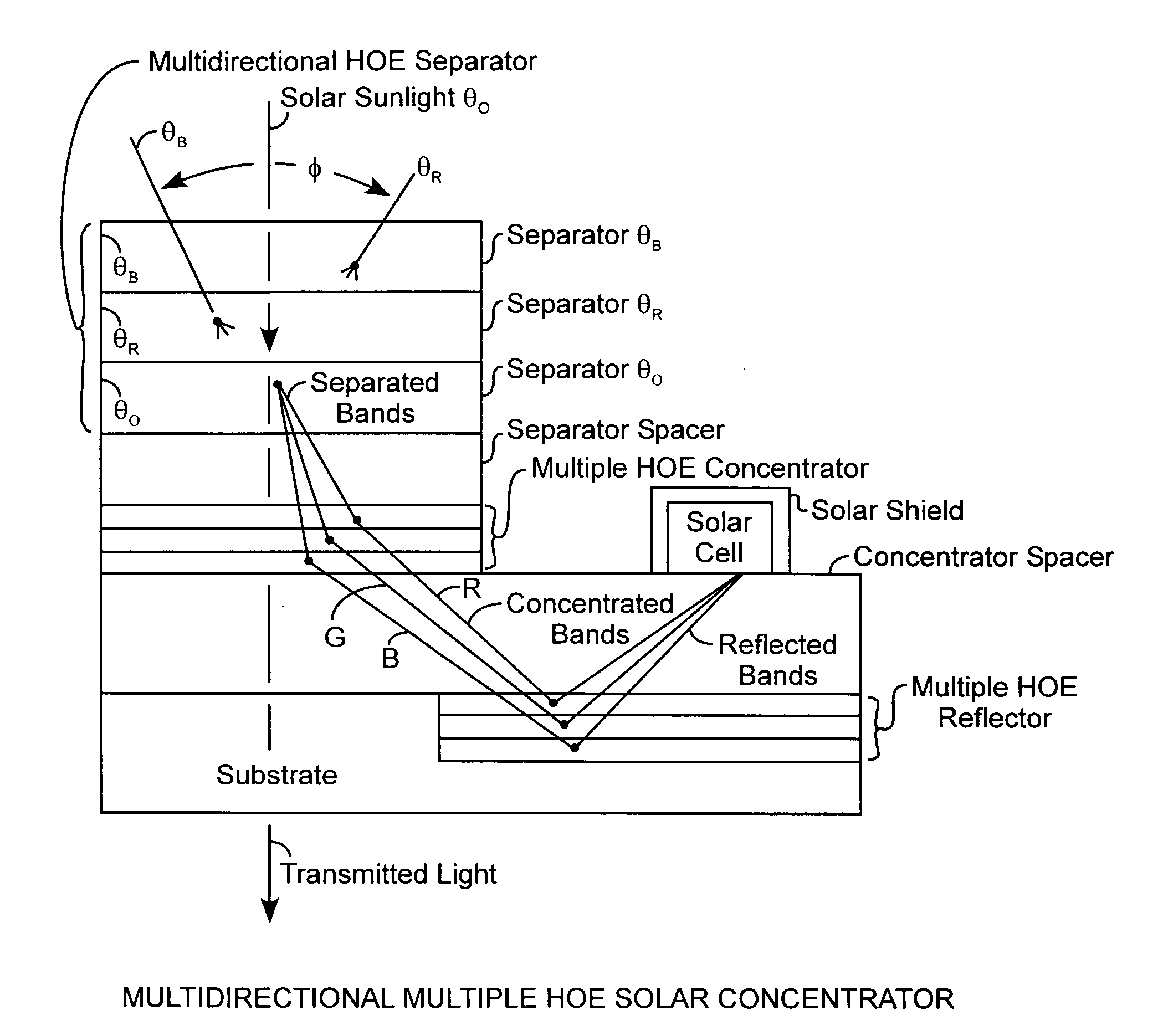
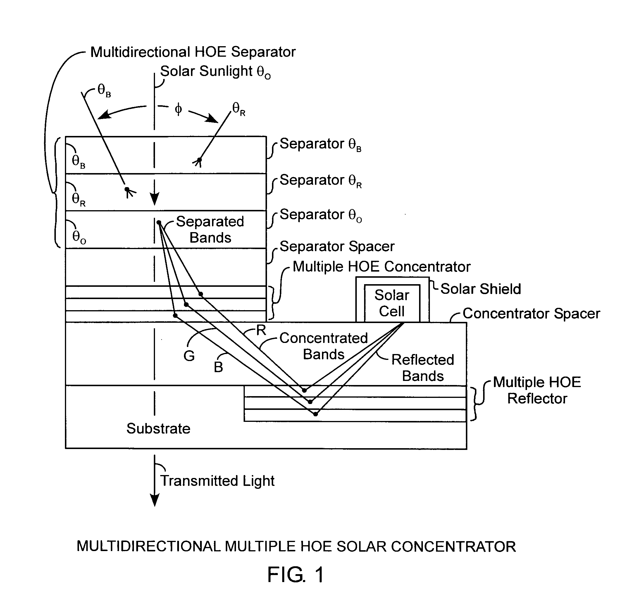
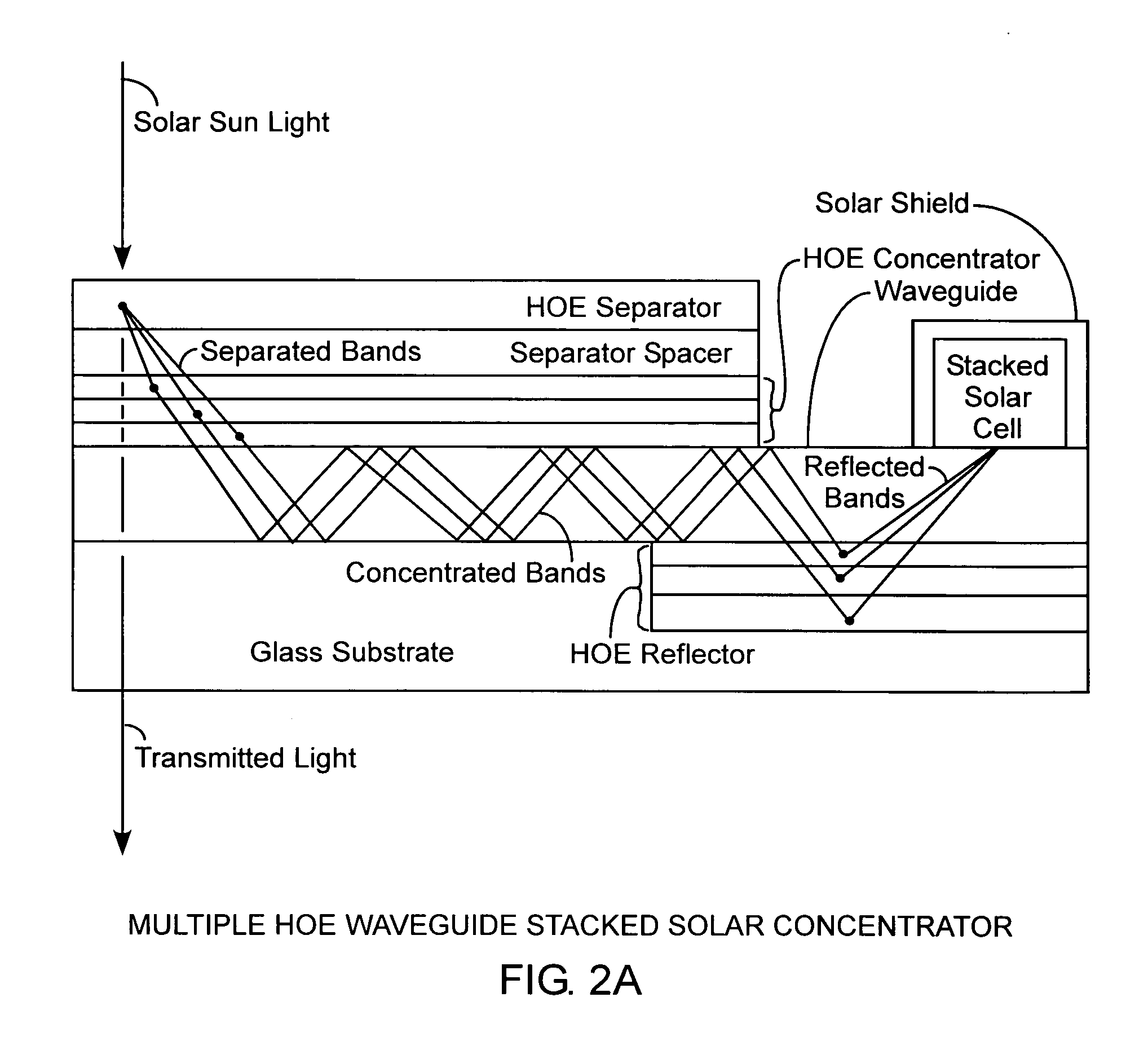
[0024]An embodiment of the invention is described with reference to the figures using reference designations as shown in the figures. Referring to FIG. 1, a multidirectional multiple holographic element (HOE) solar concentrator received solar sunlight by one or more HOE separators, such as HOE separators θB, θO, and θR for defining a field of view φ. The HOE separators θB, θO, and θR are collectively referred to as a multidirectional HOE separator, or simply the HOE separator. The HOE separator allows for the separation of the incident solar sunlight into separated optical bands. The separated bands are directed through a separator spacer to a multiple HOE concentrator having a plurality of individual respective HOE concentrators, each of which are for concentrating the separated bands into respective concentrated bands that may be for example blue, red, and green colored optical wavelength bands. Each of the HOE separators θB, θO, and θR can be multiplexed in the same hologram volu...


PUM


Abstract

A solar concentrator receives sunlight for generating solar power with the concentrator including holographic optical element (HOE) separators for separating sunlight into separated bands, including HOE concentrators for concentrating the separated bands into concentrated bands, including HOE reflectors for reflecting the concentrated bands as reflected bands onto a multiple junction photovoltaic solar cell for generating the solar power with reduced aberrations of the bands for improved conversion of the solar light into the generator solar power, all of which can be constructed in an integrated structure using spacers, waveguides, and a substrate, where the HOEs use chirp Bragg gratings for reducing optical aberrations of the separated, concentrated, and reflected optical bands, with the option of multiple HOE separators for receiving sunlight from various angles of incidence.

Description

FIELD OF THE INVENTION [0001]The invention relates to the field of solar concentrators. More particularly the present invention relates to a solar concentrator using holographic optical processes.BACKGROUND OF THE INVENTION[0002]Future high-power space missions will demand more solar array power with longer lifetimes. One method of increasing solar array power is the use of concentrating systems that increase the amount of incident sunlight for each solar cell. In the last three decades, several solar concentrator designs based on reflective, refractive, fiber-optic, and holographic systems have been developed. While some of these technologies have been developed mostly for terrestrial applications, with a promise of low-cost, high-levels of performance, and simplified manufacturing, few have been developed for space and on the move communication applications. Even for these systems, the solar conversion efficiency is low. In addition, for some solar power systems, the designs requi...

Claims


Application Information

Patent Timeline
IPC IPC(8): H01L31/00
CPCY02E10/52H01L31/0547
Inventor OKOROGU, ALBERT O.MARVIN, DEAN C.LIU, SIMON H.PRATER, ALONZO
Owner THE AEROSPACE CORPORATION
Learn More