

Compound for use in organic electroluminescent device and organic electroluminescent device
- Summary
- Abstract
- Description
- Claims
- Application Information
AI Technical Summary
Benefits of technology
Problems solved by technology
Method used
Image

Examples
example 1
[0049]In a 2000-ml three-necked flask that had been deaerated and filled with nitrogen were placed 33.3 g (297.0 mmoles) of 1,2-cyclohexanedione and 86.0 g (594.7 mmoles) of phenylhydrazine hydrochloride, then 1000 ml of ethanol was added, and the mixture was stirred. To the flask was added dropwise 3.0 g (30.6 mmoles) of concentrated sulfuric acid over 5 minutes. The mixture was then heated to 65° C. and stirred at this temperature for 4 hours. The mixture was cooled to room temperature and the violet brown crystals formed were collected by filtration, reslurried twice with 500 ml of ethanol, and dried under reduced pressure to give 80.0 g (280.5 mmoles, 96.3% yield) of a violet brown powder.
[0050]Then, 72.0 g (261.5 mmoles) of the violet brown powder obtained above was placed in a 1000-ml three-necked flask, 720 g of acetic acid and 72.0 g of trifluoroacetic acid were added, and the mixture was stirred. The mixture was then heated to 100° C. and stirred at this temperature for 15 ...
example 2
[0056]Compound 3 was deposited on a glass substrate from an evaporation source at a rate of 0.1 nm / sec to a thickness of 50 nm by the vacuum deposition process at a degree of vacuum of 4.0×10⁻⁴ Pa. The thin film thus formed was evaluated by a fluorometer and emission of light was observed.
[0057]Separately, Compound 3 and Ir(ppy)3 were co-deposited on a glass substrate from different evaporation sources at a rate of 0.1 nm / sec to a thickness of 50 nm by the vacuum deposition process at a degree of vacuum of 4.0×10⁻⁴ Pa while controlling the concentration of Ir(ppy)3 at 7.0%. The thin film thus formed was evaluated by a fluorometer. The maximum absorption wavelength of Compound 3 was used as the excitation wavelength and the light then emitted was observed and compared with the light emitted from the thin film of Compound 3 alone. The results are shown in Table 1.
example 3
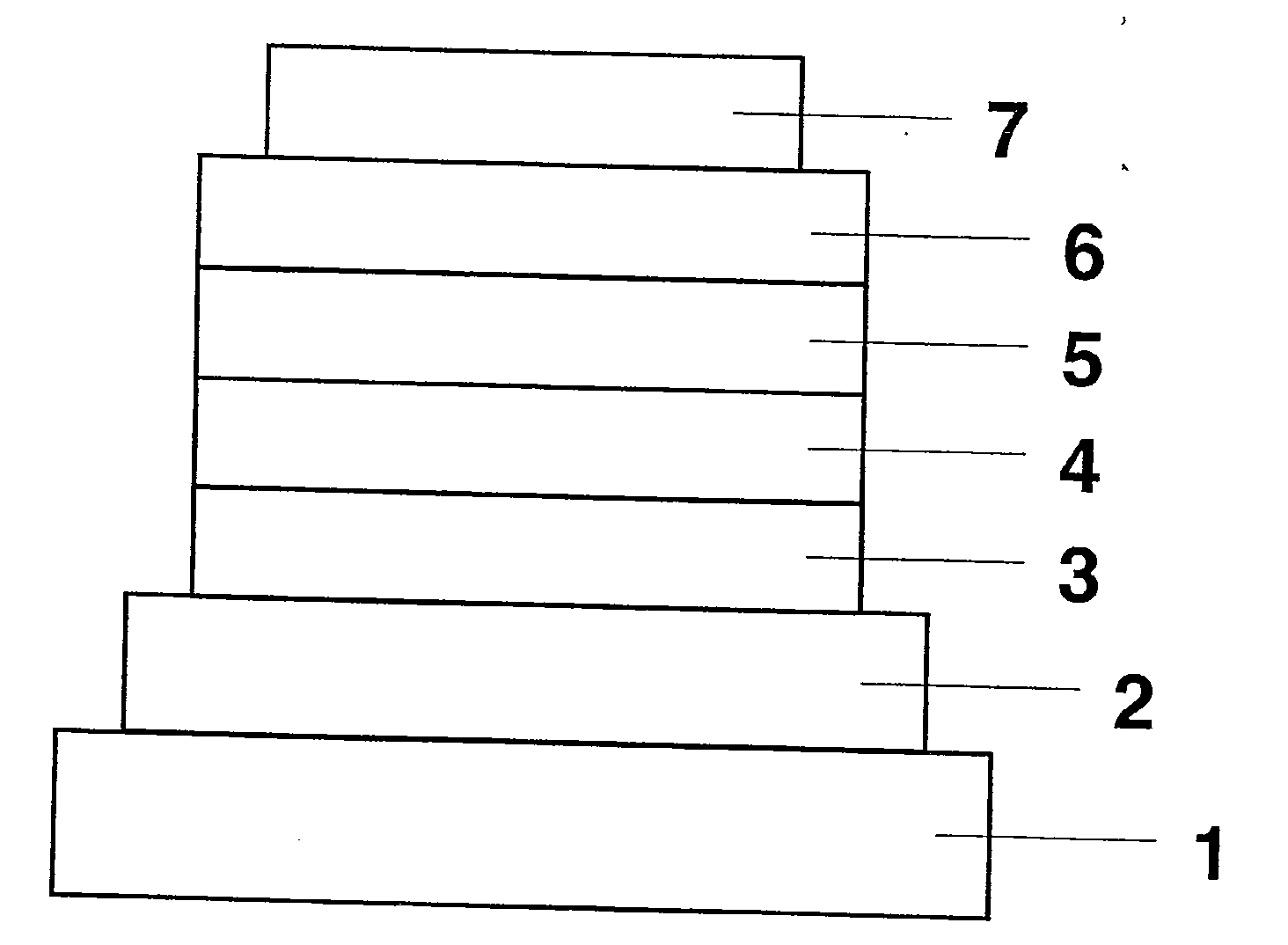
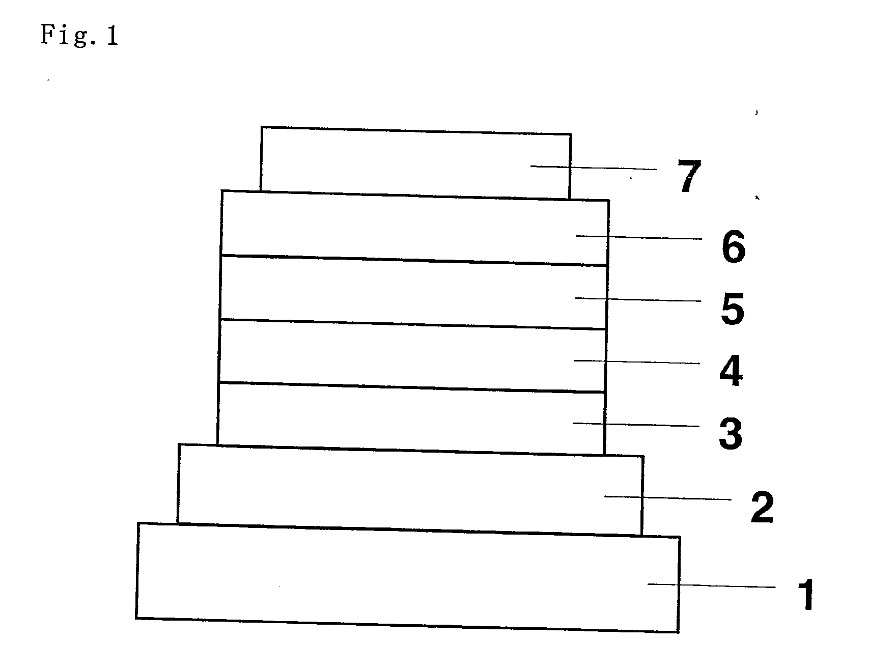
[0060]An organic EL device was fabricated as in FIG. 1 with omission of a hole-injecting layer and addition of an electron-injecting layer. Applying the vacuum deposition process at a degree of vacuum of 4.0×10⁻⁴ Pa, the constituent layers were stacked one upon another on a glass substrate having a 150 nm-thick ITO anode formed thereon. First, NPB was deposited on the ITO anode to a thickness of 60 nm to form a hole-transporting layer.
[0061]Next, Compound 3 and Ir(ppy)3 were co-deposited from different evaporation sources on the hole-transporting layer to a thickness of 25 nm to form a light-emitting layer. The concentration of Ir(ppy)3 at this point was 7.0 wt %. Then, Alq3 was deposited to a thickness of 50 nm to form an electron-transporting layer. Further, lithium fluoride (LiF) was deposited on the electron-transporting layer to a thickness of 0.5 nm to form an electron-injecting layer. Finally, aluminum (Al) as an electrode was deposited on the electron-injecting layer to a th...
PUM
| Property | Measurement | Unit |
|---|---|---|
| Electric potential / voltage | aaaaa | aaaaa |
| Electric potential / voltage | aaaaa | aaaaa |
| Electric potential / voltage | aaaaa | aaaaa |
Abstract
Description
Claims
Application Information