Method And Apparatus for Microcontact Printing of MEMS

Active Publication Date: 2010-07-29
MASSACHUSETTS INST OF TECH
View PDF20 Cites 24 Cited by
  • Summary
  • Abstract
  • Description
  • Claims
  • Application Information

AI Technical Summary

Benefits of technology

[0012]In one embodiment, the disclosure relates to a microcontact printing process by which continuous metal films are transferred over a relief structure to form a suspended membrane in a single step. One or more release layers are used to assist the transfer process. The disclosed embodiments are advantageous in enabling MEMS fabrication without requiring

Problems solved by technology

However, the conventional methods are limited to working within the existing silicon semiconductor-based framework.
Several challenges, including expense, limited size and form-factor, and a restricted materials set, prevent the future realization of new MEMS for applications beyond single chip or single sensor circuits.
Standard processing techniques are particularly restrictive when considering expanding into large area fabrication.
Conventional photolithography methods are also incompatible with printing flexible substrates MEMS and micro-sized sensor arrays.
Such steps require investing in and creating highly specialized mask sets which render conventional photolithography expensive and time and labor intensive.
While the initial investment can be recovered by producing large batches of identical MEMS devices, the conventional methods are cost prohibitive for small batches or for rapid prototype production.
Incorporating mechanical elements made of metal on this scale is difficult because of the residual stresses and patterning challenges of adding m

Method used


Image

  • Method And Apparatus for Microcontact Printing of MEMS
  • Method And Apparatus for Microcontact Printing of MEMS
  • Method And Apparatus for Microcontact Printing of MEMS

Examples


Embodiment Construction

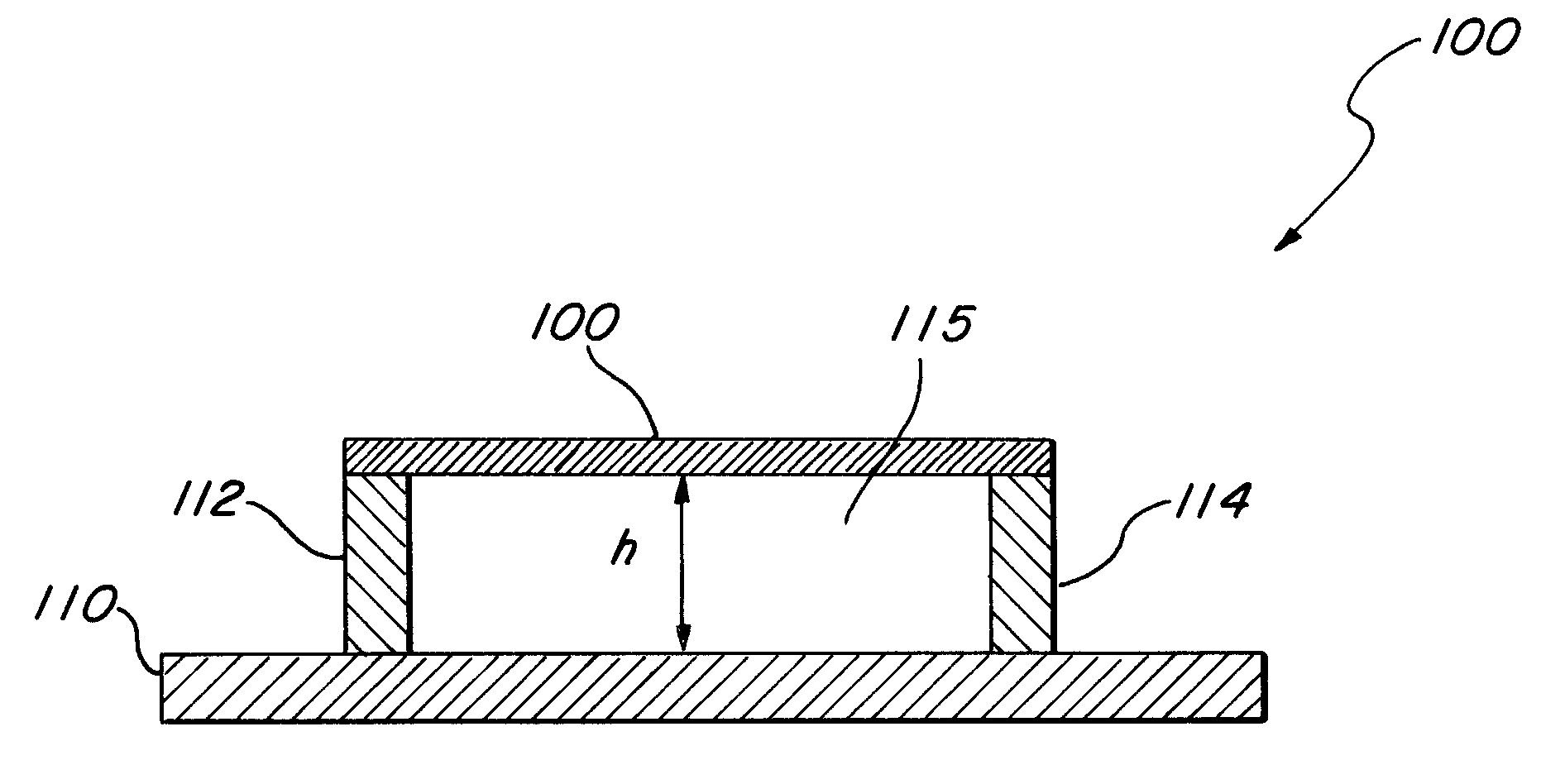
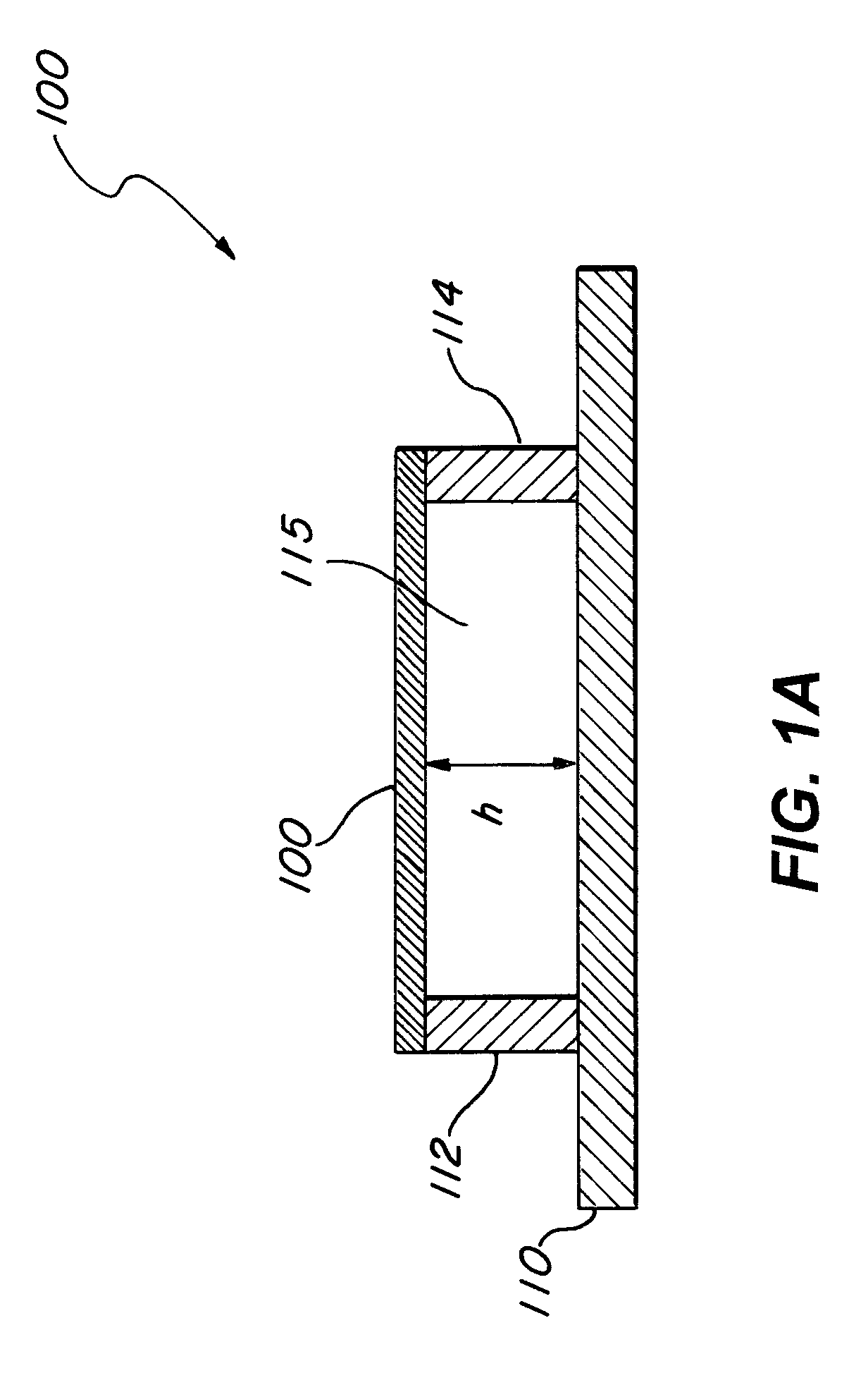
[0038]FIG. 1A is a schematic representation of a conventional MEMS device. MEMS 100 includes substrate 110 having supports 112 and 114. Supports 112 and 114 can be viewed as a plurality of ridges separated by gap 115. Supports 112 and 114 uphold layer 116. Gap 115 is defined by the separation distance between ridges 112 and by the height (h). Conventionally, layer 116 is defined by a metal layer and MEMS structure 100 is formed through photolithography as described above. As stated, the conventional processes lacked ability to produce MEMS devices over large areas and on flexible substrates.

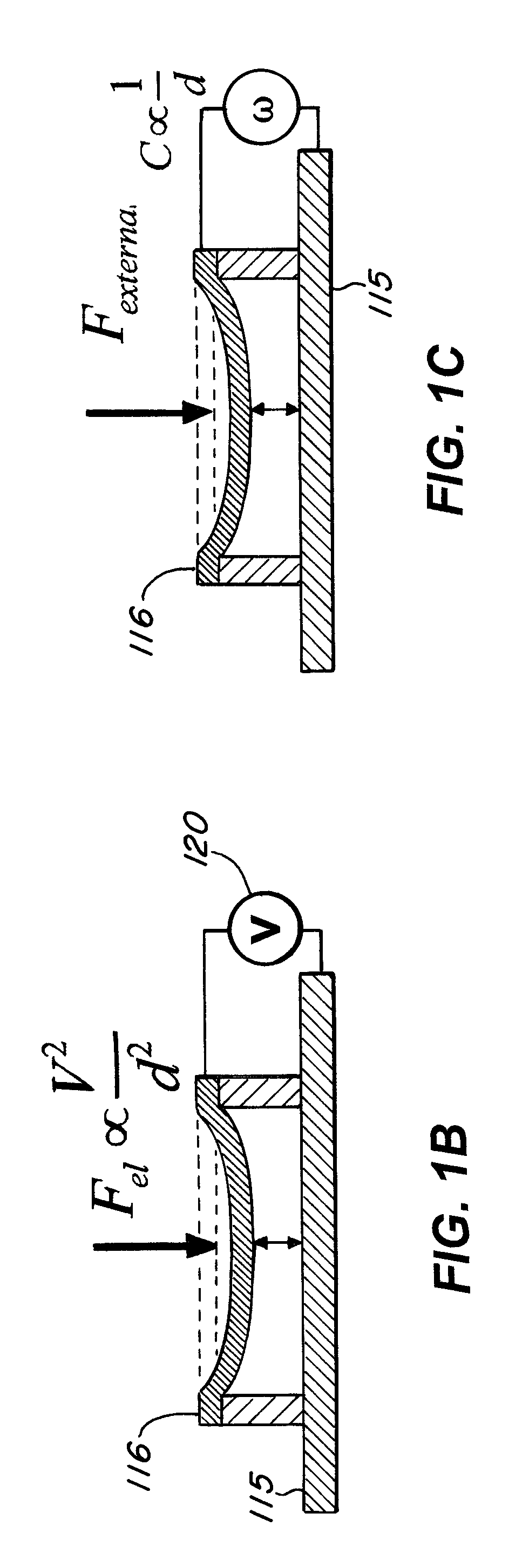
[0039]FIG. 1B shows an application of the MEMS device of FIG. 1A used as an actuator. In FIG. 1B, structure 100 is connected to voltage source 120 through substrate 115 and diaphragm 116 which act as electrodes. The bias provided by voltage source 120 creates an electrostatic force between electrode 115 and layer 116, causing the latter to act as a diaphragm by deflecting towards electrode 115. T...


PUM

PropertyMeasurementUnit
Lengthaaaaaaaaaa
Speedaaaaaaaaaa
Speedaaaaaaaaaa

Abstract

The embodiments disclosed herein are directed to fabrication methods useful for creating MEMS via microcontact printing by using small organic molecule release layers. The disclose method enables transfer of a continuous metal film onto a discontinuous platform to form a variable capacitor array. The variable capacitor array can produce mechanical motion under the application of a voltage. The methods disclosed herein eliminate masking and other traditional MEMS fabrication methodology. The methods disclosed herein can be used to form a substantially transparent MEMS having a PDMS layer interposed between an electrode and a graphene diaphragm.

Description

[0001]The application claims the filing-date priority of Provisional Application No. 61 / 138,014, filed Dec. 16, 2008, the disclosure of which is incorporated herein in its entirety.[0002]This invention was made with government support under grant number HR0011-06-1-0045 awarded by the Defense Advanced Research Projects Agency. The government has certain rights in this invention.BACKGROUND[0003]1. Field of the Invention[0004]The disclosure relates to a method and apparatus for microcontact printing of microelectro-mechanical systems (“MEMS”). More specifically, the disclosure relates to a novel method and apparatus for direct patterning of metallic MEMS through microcontact printing.[0005]2. Description of Related Art[0006]MEMS applied over large areas would enable applications in such diverse areas as sensor skins for humans and vehicles, phased array detectors and adaptive-texture surfaces. MEMS can be incorporated into large area electronics. Conventional photolithography-based me...

Claims


Application Information

Patent Timeline
IPC IPC(8): H01G7/00B29C63/00
CPCY10T29/49105Y10T29/4902Y10T156/1168Y10T29/435Y10T29/49002B81C1/0046B81C2201/0185Y10T29/43B81B2201/042
Inventor BULOVIC, VLADIMIRPACKARD, CORINNE EVELYNJONG-HUA YU, JENNIFERMURARKA, APOORVAKIM, LEEANN
Owner MASSACHUSETTS INST OF TECH
Why Eureka
Try Eureka