Transient voltage suppression circuit for an implanted RFID chip

a technology of transient voltage suppression and implanted rfid, which is applied in the field of high-voltage circuit protection, can solve the problems of limited information so provided, difficult to identify, and often unreliable identification forms

Inactive Publication Date: 2010-07-29
WILSON GREATBATCH LTD
View PDF99 Cites 41 Cited by
  • Summary
  • Abstract
  • Description
  • Claims
  • Application Information

AI Technical Summary

Benefits of technology

[0018]In general, the present invention is directed to a system for identifying implants within a patient, comprising an implantable medical device, a radio frequency identification (RFID) tag having a hermetically sealed chip and biocompatible antenna and being associated with the implantable medical device, the RFID tag containing information relating to the patient and/or the implantable medical device, and an interrogator capable of communicating with the RFID tag. More particularly, the present invention is directed to transient voltage suppress

Problems solved by technology

The information so provided is limited due to space and typically includes only the manufacturer and model number of the implanted device.
However, such forms of identification are often not reliable.
In addition, there have been a number of situations where the patient (due to dementia or Alzheimer's, etc.) cannot clearly state that he or she even has a pacemaker.
If the patient is comatose, has low blood pressure, or is in another form of cardiac distress, this presents a serious dilemma for the ER.
What happens next is both laborious and time consuming.
It is a very difficult surgical procedure to actually remove leads from the heart once they are implanted.
This is because the distal TIP and other areas of the leads tend to become embedded and overgrown by tissue.
It often takes very complex surgical procedures, including lasers or even open heart surgery, to remove such lead wire systems.
However, it is also quite common for leads to fail for various reasons.
They could fail due to breakdown of electrical insulation or they could migrate to an improper position within the heart.
Abandoned leads can be quite a problem during certain medical diagnostic procedures, such as MRI.
It has been demonstrated in the literature that such leads can greatly

Method used


Image

  • Transient voltage suppression circuit for an implanted RFID chip
  • Transient voltage suppression circuit for an implanted RFID chip
  • Transient voltage suppression circuit for an implanted RFID chip

Examples


Embodiment Construction

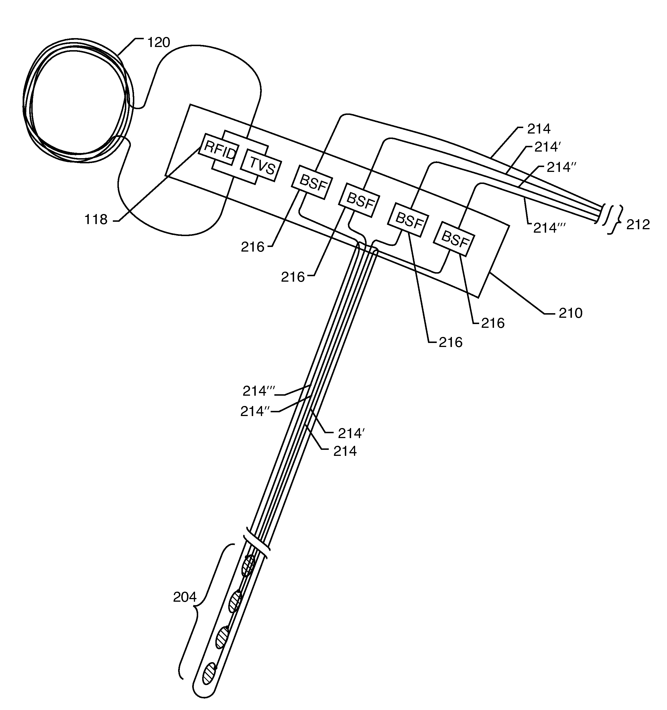
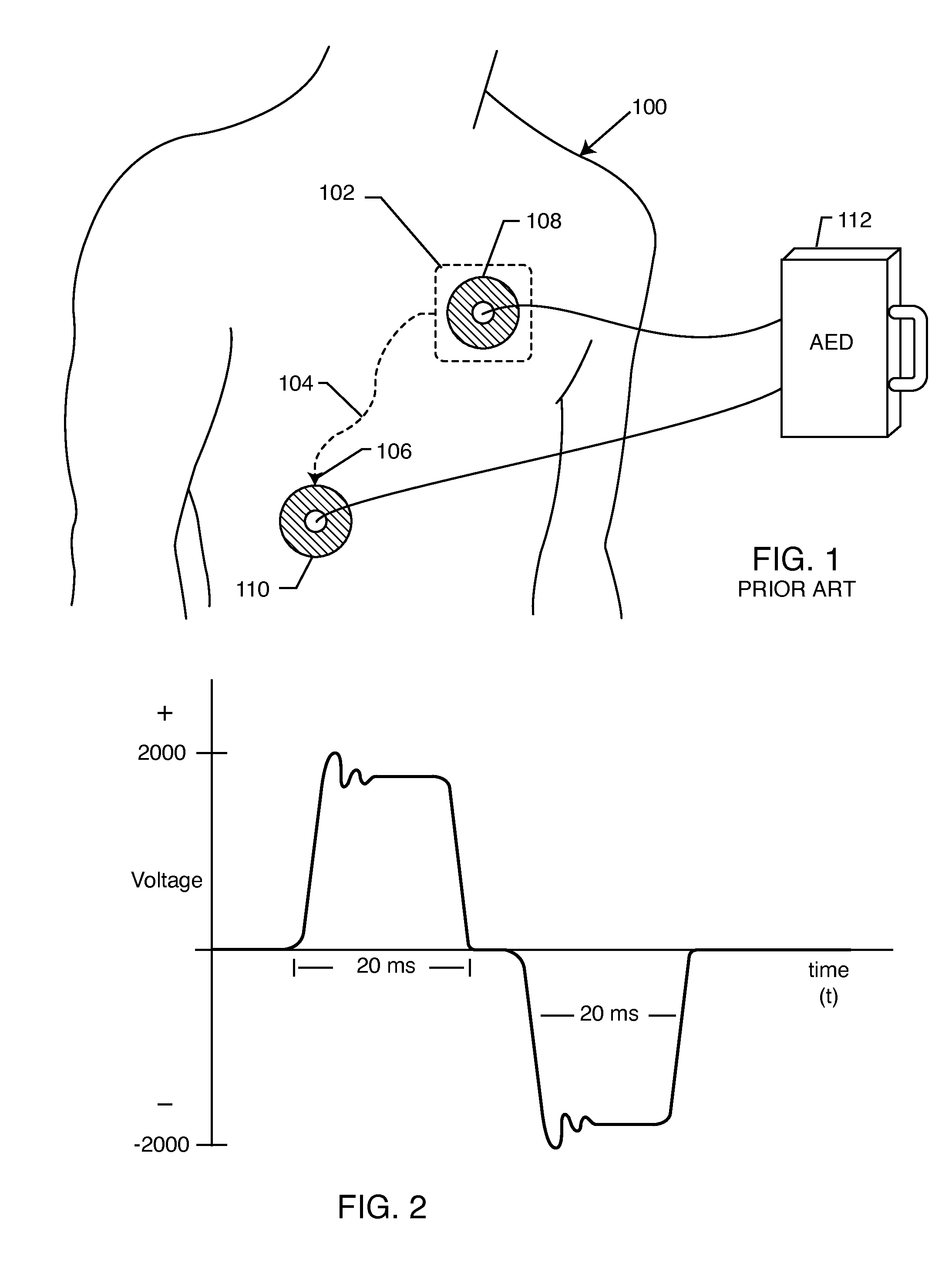
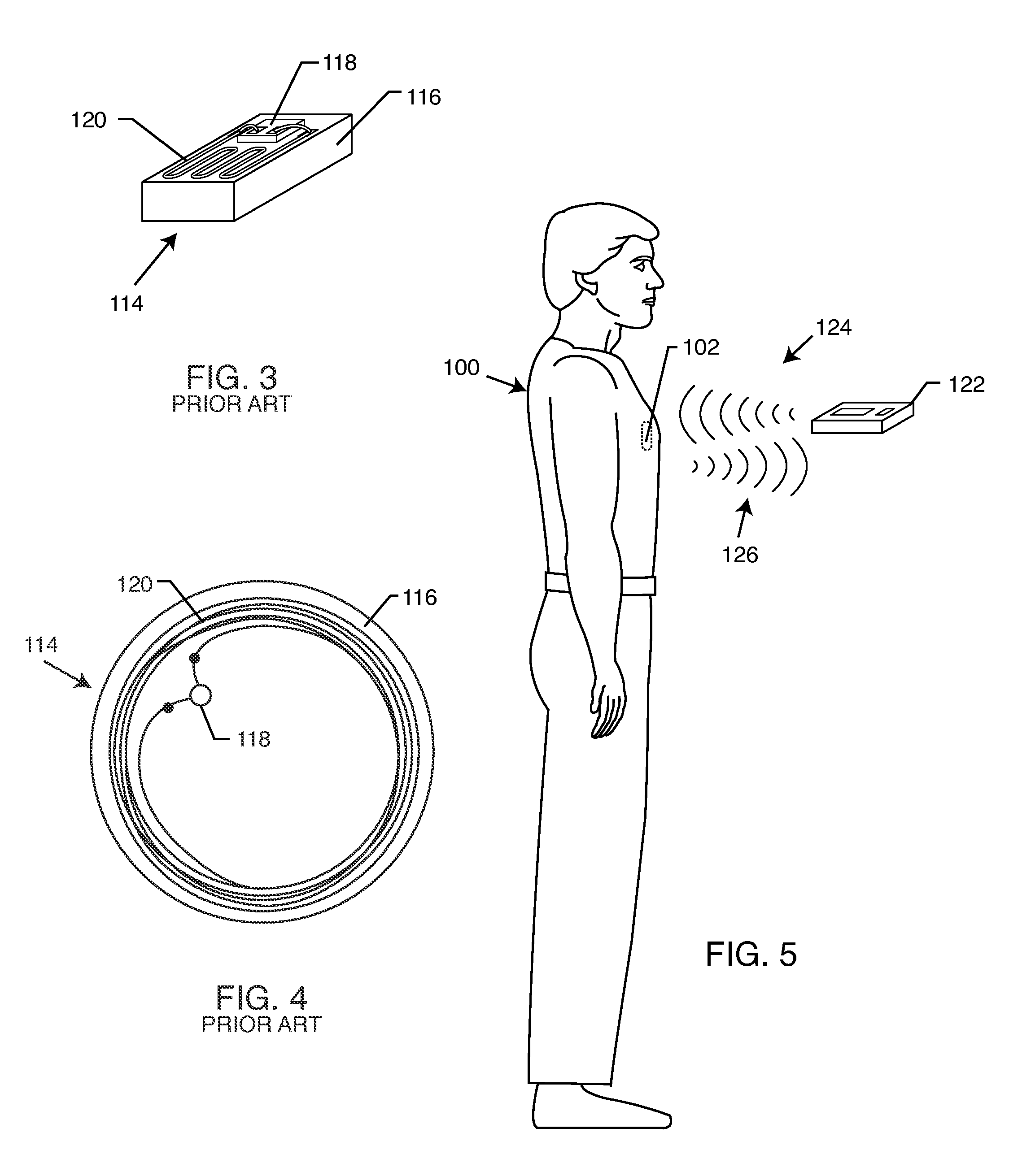
[0052]The present invention is directed to a radio frequency identification (RFID) system for use with active implantable medical devices (AIMDs) 102 and an associated RFID tag 114. Specifically, the RFID system comprises an RFID tag 114 implanted in a patient's body and associated with an implanted AIMD 102 or component, and an interrogator 122 in communication with the RFID tag 114.

[0053]More particularly, the present invention resides in circuit protection devices for RFID microchips 118. Such circuit protection devices can be a diode, a Zener diode, an avalanche diode, Zener connected series opposing (back-to-back) diodes, or just a general TVS diode. Transient voltage suppression diodes are electronic components used to protect sensitive circuits from voltage spikes induced on connected wires. In the case of an RFID chip 118, the connected wire is its own antenna. TVS diodes are also commonly referred to as transorbs after the brand name TransZorb, registered by General Semicon...


PUM


Abstract

A transient voltage suppressing (TVS) circuit includes an implantable RFID chip, an antenna associated with the RFID chip, and a transient voltage suppressor electrically connected in parallel to both the RFID chip and the antenna. The transient voltage suppressor may be formed of an array of diodes, such as back-to-back diodes, at least one Zener diode, or back-to-back or series opposing Zener diodes. In preferred embodiments, the antenna is formed of a biocompatible material suitable for long-term exposure to body tissue and body fluids, and the RFID chip and the transient voltage suppressor are disposed within a hermetically sealed biocompatible container.

Description

BACKGROUND OF THE INVENTION[0001]This invention relates generally to high voltage circuit protection of implantable and biocompatible radio frequency identification (RFID) tags and associated antennas which may be used with medical devices or for general personal identification purposes. More particularly, high voltage or transient voltage suppression (TVS) circuits are described which protect the sensitive RFID microchip from shorting out in the presence of an over-voltage such as caused by some types of surgical equipment and automatic external defibrillators (AEDs).[0002]There are known in the art various methods for identifying implanted medical devices. One such method is the use of X-ray identification tags encapsulated within header blocks of pacemakers or implantable cardioverter defibrillators (ICD). Such X-ray identification tags can be read on an X-ray of the implanted device and provide information to the physician. The information so provided is limited due to space and...

Claims


Application Information

Patent Timeline
IPC IPC(8): A61N1/08A61N1/36
CPCA61B5/0031G06K19/07749A61B2019/448A61B2562/08A61N1/0534A61N1/0539A61N1/36021A61N1/36071A61N1/36082A61N1/37A61N1/3718A61N1/37223A61N1/37229A61N1/37276A61N1/3752A61N1/3758A61N2001/086G06K19/0701G06K19/0715A61B19/44A61B90/90A61B90/98A61N1/086
Inventor STEVENSON, ROBERT A.FRYSZ, CHRISTINE A.
Owner WILSON GREATBATCH LTD
Why Eureka
Try Eureka