Matrix Drill Bit with Dual Surface Compositions and Methods of Manufacture

a technology of matrix drill bit and composition, which is applied in the direction of grinding device, borehole/well accessories, other chemical processes, etc., can solve the problems of affecting affecting the performance of matrix drill bit, so as to improve the life of matrix drill bit and/or the associated life. , to achieve the effect of improving the performance of downhole drilling

Inactive Publication Date: 2010-08-05
HALLIBURTON ENERGY SERVICES INC
View PDF5 Cites 41 Cited by
  • Summary
  • Abstract
  • Description
  • Claims
  • Application Information

AI Technical Summary

Benefits of technology

[0010]One aspect of the present disclosure may include placing one or more layers of one or more hard materials at selected locations in a mold corresponding generally with respective selected locations on exterior portion of blades, cutter pockets, junk slots and / or other components of an associated matrix bit body. A preformed hollow bit blank or casting mandrel may be disposed in the mold. One or more matrix materials may be added to the mold. The matrix materials may be selected to form a hard, matrix bit body. A binder material may also be added to the mold. During heating of the mold, liquid binder material may flow through the matrix materials and the one or more layers of the hard material. The layer or layers of hard material may provide desired enhancement to resist erosion, abrasion, wear, impact and / or fatigue forces at respective selected locations on exterior portions of the matrix bit body.
[0011]For some applications, a composite layer of hard material may be disposed at selected locations on exterior portions of a matrix bit body in accordance with teachings of the present disclosure. Each composite layer of hard material may include two, three or more smaller (thinner) layers or sublayers of hard material. Each sublayer of hard material may include a plurality of large hard particles including, but not limited to, low alloy sintered materials in the form of pellets and / or low alloy sintered material in the form of crushed powder. Other forms of low alloy sintered material may also be used to enhance downhole drilling performance and / or associated matrix drill bit life.
[0012]For some applications, a low percentage of binder material (4% plus or minus 1% Co, Ni, B, Mo, Cr or Se binder or any combination thereof) may be used to bind fine tungsten carbide grains to form generally spherical tungsten carbide particles or pellets. The use of such particles or pellets may provide substantially increased carbide content at one or more selected locations on exterior portions of an associated matrix body as compared to hard materials with twenty to thirty percent (20% to 30%) binder. For some applications, the size of the resulting tungsten carbide particles or pellets may be substantially enlarged such that only one layer of the second hard material is required to provide satisfactory resistance to erosion, abrasion, impact and / or fatigue forces at a selected location. Used matrix drill bits may be repaired by forming one or more layers of hard material at selected locations on exterior portions of an associated matrix bit body.

Problems solved by technology

Since machining hard, abrasion, erosion and / or wear resistant materials is generally both difficult and expensive, it is common practice to form some metal parts with a desired configuration and subsequently treat one or more portions of the metal part to provide desired abrasion, erosion and / or wear resistance.
Apply hard facing to matrix materials such as a matrix bit body is often more difficult and technically challenging as compared with applying the same hardfacing to a generally uniform, non-matrix metal surface.

Method used


Image

  • Matrix Drill Bit with Dual Surface Compositions and Methods of Manufacture
  • Matrix Drill Bit with Dual Surface Compositions and Methods of Manufacture
  • Matrix Drill Bit with Dual Surface Compositions and Methods of Manufacture

Examples


Embodiment Construction

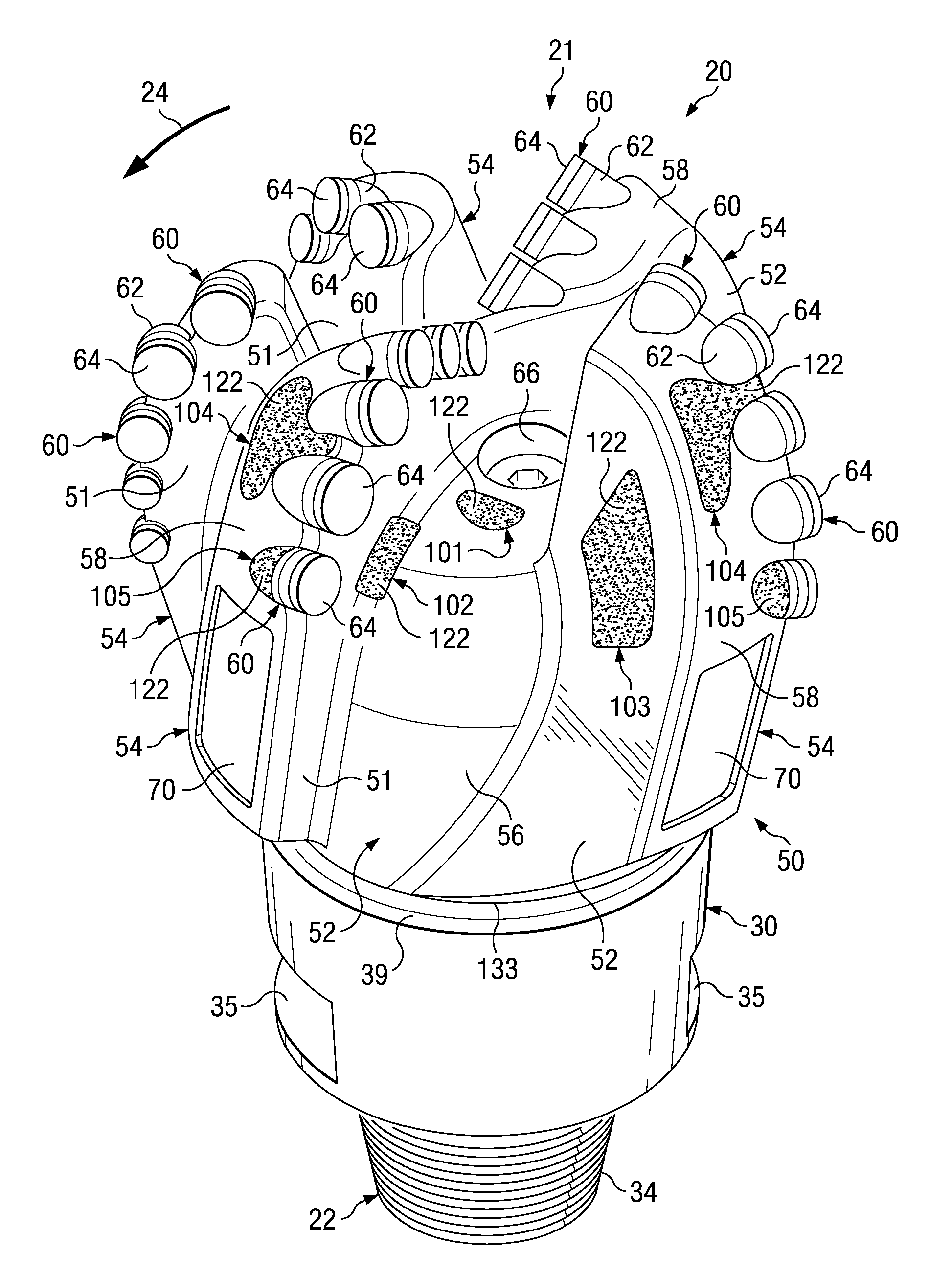
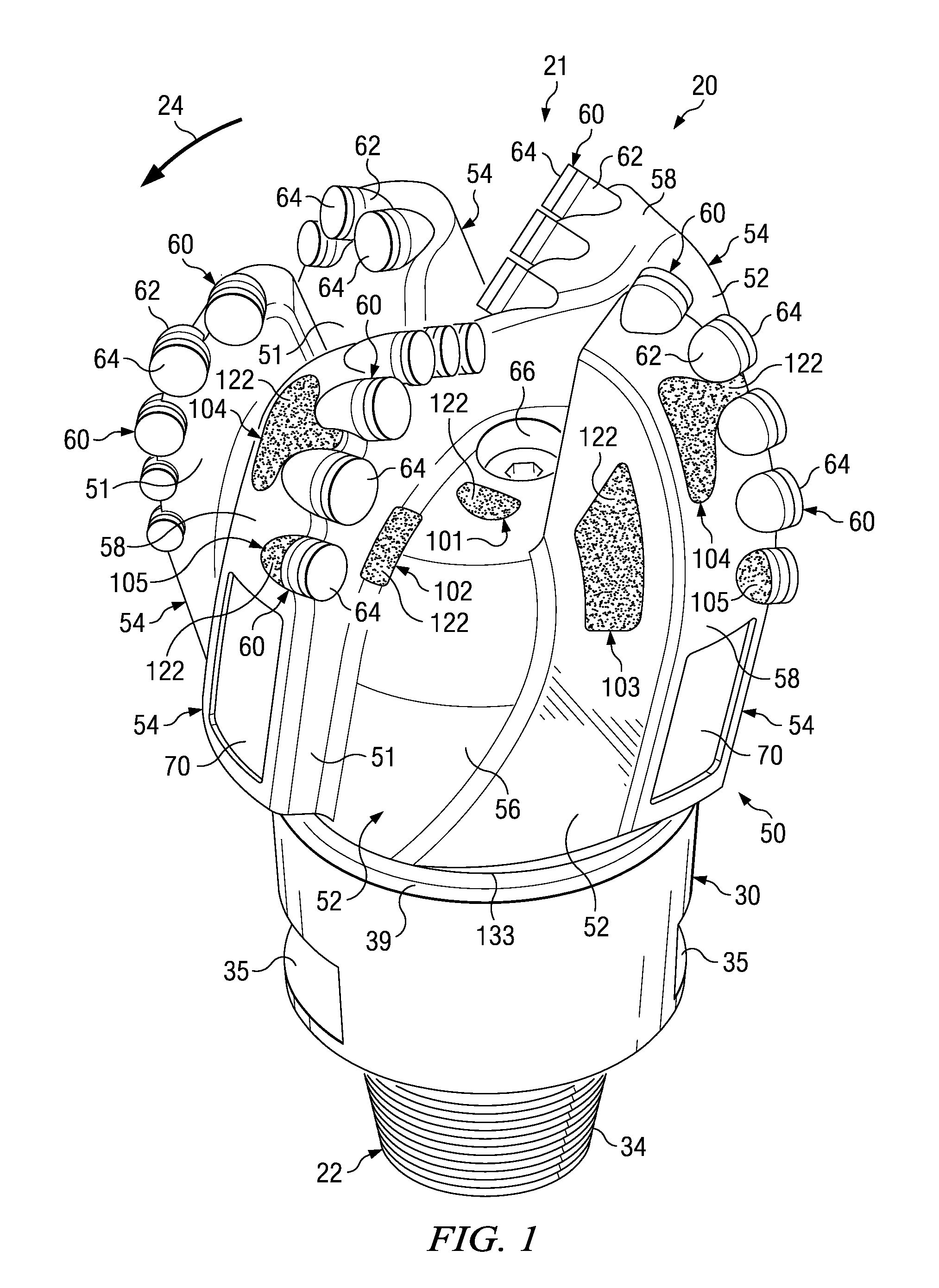
[0031]Preferred embodiments and various advantages may be understood by referring in more detail to FIGS. 1-6 of the drawings, in which like numerals refer to like parts.

[0032]The terms “matrix bit”, “matrix drill bit” and “matrix rotary drill bit” may be used in this application to refer to “rotary drag bits”, “drag bits”, “fixed cutter drill bits” or any other drill bit incorporating teaching of the present disclosure. Such drill bits may be used to form well bores or boreholes in subterranean formations.

[0033]Matrix drill bits incorporating teachings of the present disclosure may include a matrix bit body formed by one or more matrix materials. For other embodiments (not expressly shown) a matrix bit body may be formed with at least a first matrix material and a second matrix material. For some applications the first matrix material may have increased toughness or high resistance to fracture and also provide erosion, abrasion and wear resistance. The second matrix material (not e...


PUM

PropertyMeasurementUnit
thicknessaaaaaaaaaa
thicknessaaaaaaaaaa
thicknessaaaaaaaaaa

Abstract

Matrix drill bits and other downhole tools may be formed with one or more layers of hard materials disposed on exterior portions thereof. Exterior portions of used rotary drill bits or other downhole tools may be measured using three dimensional (3D) scanning techniques or other techniques to determine specific locations of undesired abrasion, erosion and/or wear. During the design of a new rotary drill bit or other downhole tool, computational flow analysis techniques may be used to determine potential locations for excessive erosions, abrasion, wear, impact and/or fatigue on exterior portions of the rotary drill bit or other downhole tools. One or more layers of hard material may be disposed at such locations on exterior portions of matrix bit bodies and other matrix bodies based on analyzing exterior portions of used downhole tools and/or computational flow analysis.

Description

RELATED APPLICATION[0001]This application claims the benefit of U.S. provisional application Ser. No. 61 / 148,665 entitled “Matrix Drill Bit With Dual Surface Compositions And Methods of Manufacture” filed Jan. 30, 2009, the contents of which is hereby incorporated by reference in its entirety.TECHNICAL FIELD[0002]The present disclosure relates in general to matrix drill bits and other well tools with matrix bodies having one or more layers of hard material disposed at selected locations on exterior portions thereof and, more particularly, to forming one or more layers of hard material at selected locations during manufacture of a matrix body or applying one or more layers of hard material at selected locations on exterior portions of a used matrix body.BACKGROUND OF THE DISCLOSURE[0003]Rotary drill bits are frequently used to drill oil and gas wells, geothermal wells and water wells. Rotary drill bits may be generally classified as rotary cone or roller cone drill bits and fixed cut...

Claims


Application Information

Patent Timeline
Patent Type & Authority Applications(United States)
IPC IPC(8): E21B10/55E21B10/42E21B10/60B24D3/00
CPCB22F3/26B22F7/08B22F2005/001E21B10/602B24D18/0009E21B10/55C22C29/08E21B10/46
Inventor LIND, WILLIAM H.BIRD, JAY S.
Owner HALLIBURTON ENERGY SERVICES INC
Why Eureka
Try Eureka