[0009]The invention, in one embodiment, features
adaptive optics (AO) integrated into a
line scanning opthalmoscope (LSO). The invention fills the niche between SLO instruments that provide
wide field but limited resolution for routinely clinical use and the complex,
high resolution, high-performance AO instruments. A compact, simplified AO instrument like the AO-LSO, which can be used by ophthalmologists, optometrists, and vision scientists, can advance the understanding of vision and the development of new techniques to detect and treat
retinal diseases.
[0010]An AO-LSO can provide
lateral resolution sufficient to visualize the cells and structures critical for vision. An AO-LSO has simplied
optics, high-speed scanning components, and smaller
footprint compared to a traditional research AOSLO. An AO-LSO can be used to visualize, for example, photoreceptors, fine capillaries,
nerve fiber bundles, and
drusen, new vessel growth, and lesions in a diseased eye. This advance in compact and lower-cost
instrumentation can allow for more rapid transition of
high resolution AO capabilities to routine clinical use to provide efficient and rapid
image acquisition,
early disease screening and detection, and enhanced diagnostic yield, and can guide existing and new treatment strategies. The capability to map and visualize
retinal structures in unprecedented detail can improve the understanding of
disease processes and improved treatment modalities.
[0011]A bench-top AO-LSO instrument can produce
high resolution retinal images with only one moving part, a smaller instrument
footprint, and fewer of optical components. The AO-LSO can have a moderate
field of view (e.g., about 5.5 deg), which allows montages of the macula or other targets to be obtained quickly and efficiently. For example, the entire macular can be rapidly mapped with a 3×3 image montage. Photoreceptors can be resolved and counted within about 0.5 mm of the fovea. The capillaries surrounding the foveal avascular zone can be resolved, as well as cells flowing within them. Individual
nerve fiber bundles can be resolved, especially near the
optic nerve head, as well as other structures such as the lamina cribrosa. In addition to
instrument design, fabrication, and testing,
software algorithms can be used for automated
image registration, cone counting, and montage stitching.
[0012]
Adaptive optics components and a
confocal line-scanning (also called line-field)
retinal imaging approach (e.g., an AO-LSO
system) can provide a reduction in
hardware complexity by
elimination of a high-speed
scanner and associated mirror or lens relays.
Lateral resolution and depth sectioning of the confocal
line scanning approach can be improved with
adaptive optics. For example, about 6-μm
diameter photoreceptors can be resolved at eccentricities of about 0.6 μm (e.g., about 2 deg.). About 15-20 μm
diameter nerve fiber bundles can be resolved in the nerve
fiber layer. The system can resolve fine capillaries surrounding the foveal avascular zone and can visualize the vacuoles in the lamina cribrosa in the
optic nerve head. In some embodiments, retinal images can be stitched to map the photoreceptor mosaic across the entire macula (e.g., about 15 deg.). Acquisition
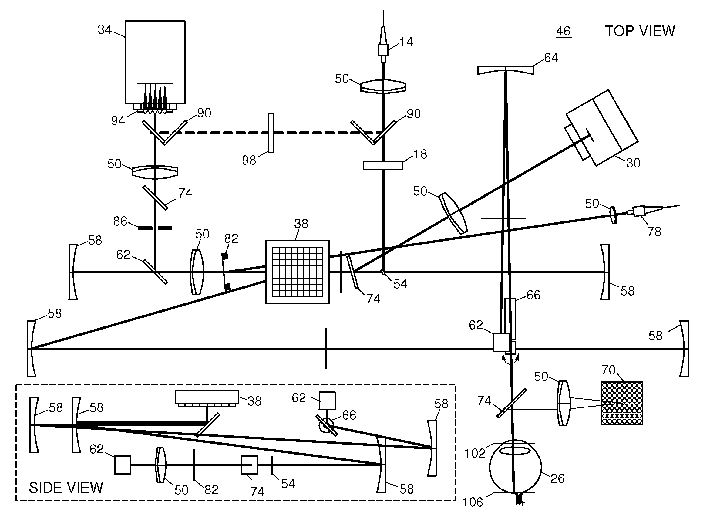
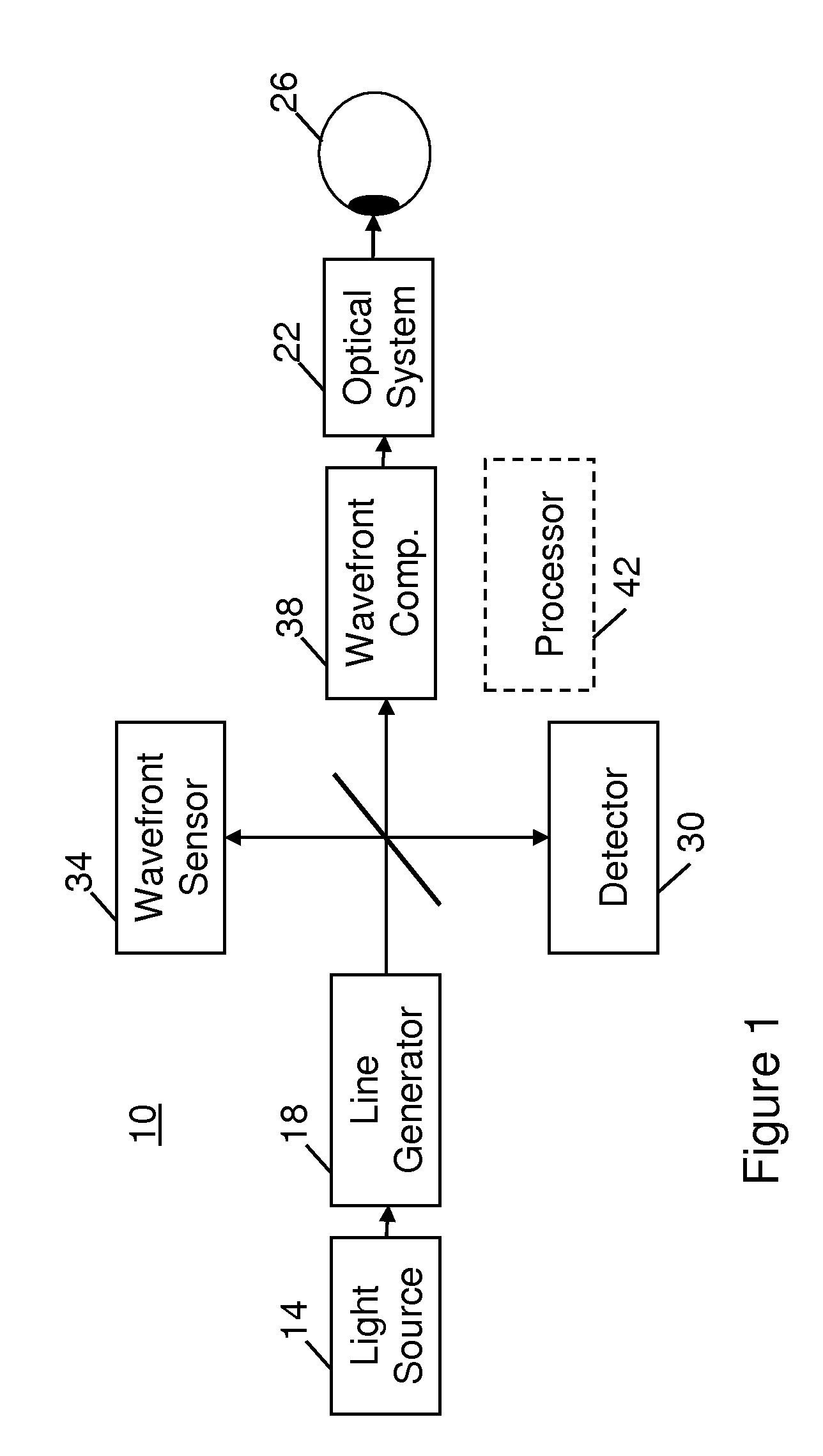
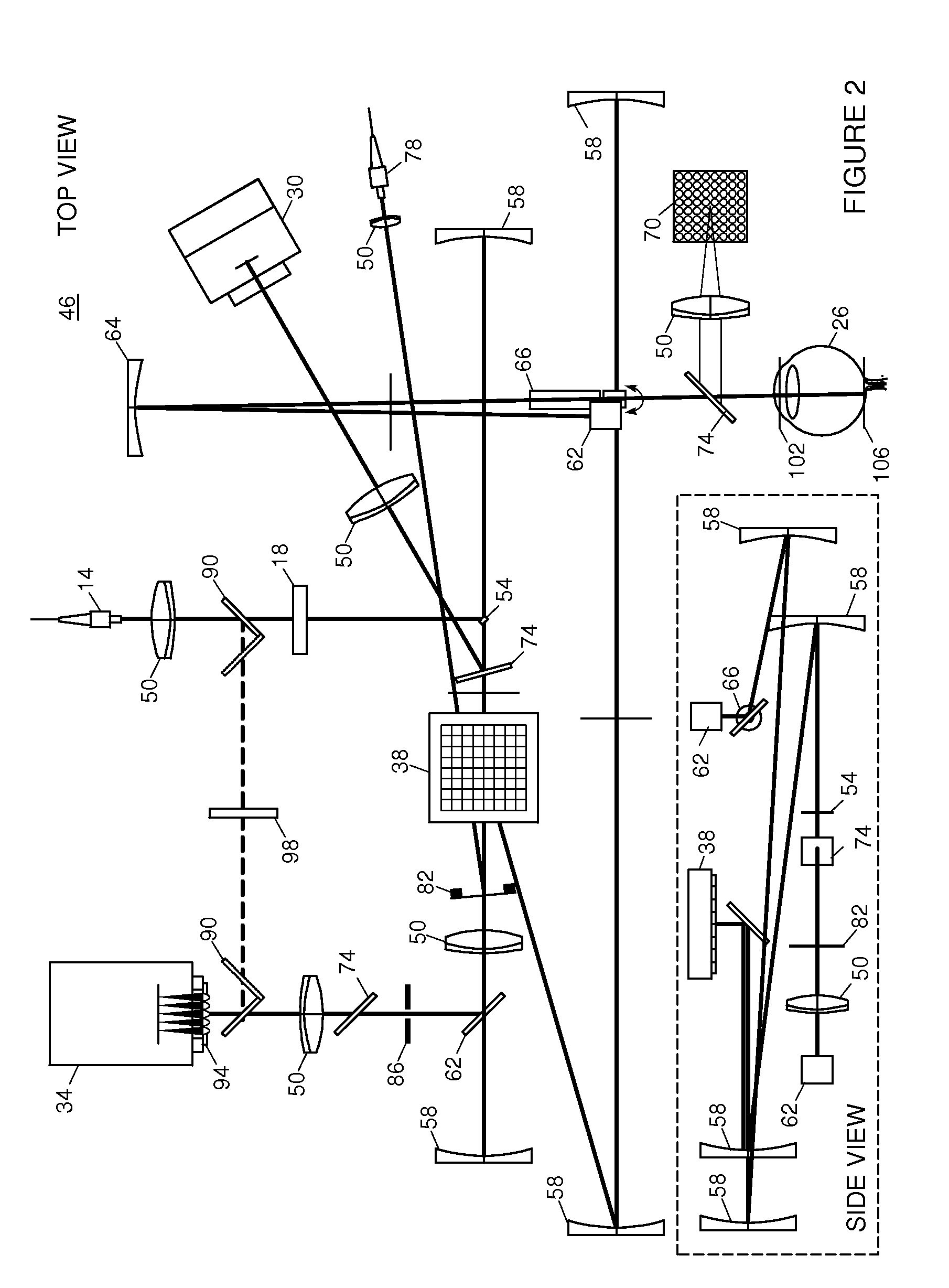
software can be used to control and synchronize instrument hardware, including the deformable minor, Hartmann-Shack
wavefront sensor (HS-WS),
galvanometer, and linear
detector. In some embodiments,
analysis software is used for automated registration and averaging, cone counting, and generation of montages. In some embodiments, the system includes a high-
stroke deformable mirror, only one moving part, half the optical elements (e.g., spherical minors) of a traditional AOSLO setup, and can feature further reduction in hardware.
[0013]The AO-LSO system can include the use of
wavefront sensorless AO control algorithms adapted to the
line scanning retinal imager.
Wavefront sensorless algorithms can extract information on ocular aberrations from the image information itself, rather than from a separate
wavefront sensor. The
algorithm can process image information efficiently enough to operate in real time (e.g., at about 10 Hz), and can obviate the need for a separate
wavefront sensor, resulting in further reduction in system complexity. With implementation of a wavefront sensorless
algorithm, the AO-LSO system can include (e.g., can be reduced to) a
deformable mirror, a linear
detector, a
galvanometer, and a spherical mirrors. The implementation of a wavefront sensorless
algorithm, therefore, not only decreases the cost to produce a device, but also enables a less complex, easier to operate instrument.

