Concurrent disposal and consolidation of dredged sediment using horizontal drains and vacuum loading

a technology of horizontal drains and sediment, applied in the direction of water/sludge/sewage treatment, rock-fill dams, chemical instruments and processes, etc., can solve the problems of cake requiring solidification/stabilization, cake may not fully meet all regulatory requirements, and contaminated sediments in many streams, rivers, lakes, etc., to achieve faster completion of the project, no waste of ponds, and low cost

Inactive Publication Date: 2010-08-12
HWANG DAEKYOO
View PDF9 Cites 10 Cited by
  • Summary
  • Abstract
  • Description
  • Claims
  • Application Information

AI Technical Summary

Benefits of technology

[0022]As the settled sediment builds up further above the consolidating layer in the disposal pond, another plurality of horizontal drains are installed at a new depth, preferably 1.8 to 3.0 m higher than the first depth in the sediment layer. Repeating this process of discharging dredged sediment and installing horizontal drains along with vacuum pumping operation allows continued dredging and discharge of sediment to fill the disposal pond with consolidated sediment. This method offers three advantages over the conventional method of complete disposal followed by consolidation using vertical wick drains (with or without vacuum): no waste of pond capacity for a large volume of fill, faster completion of the project, and project completion for a lower cost.
[0023]Upon completion of dredging and disposal operation, the surface of the disposal pond is graded with fill to achieve positive drainage and a final cover is installed to close the disposal pond as a landfill. After installing the final cover, vacuum pumping continues for some time to overconsolidate the consolidated sediment. Overconsolidation is an effective means of minimizing post-closure leachate generation and settlement of the final cover. The present invention may be used to treat contaminated sediment in the disposal pond by injecting liquid reagents via the horizontal drains for bioremediation, chemical oxidation, or stabilization. Contaminants in the sediment may be flushed out by injecting clean water or a cleaning solution through a set of horizontal drains and extracting the same through another set of horizontal drains. This treatment step may be implemented either before or after final cover installation.
[0024]The present invention can be used for dewatering, stabilization and volume reduction of any fluid earthen medium stored in a pond, such as coal ash ponds, gypsum ponds, mine tailings ponds, and sludge ponds. In addition, this invention can be used to improve the stability of large dams containing a fluid earthen medium by lowering the water level in the dam and by increasing the strength of the unstable medium behind the dam.

Problems solved by technology

Past industrial activities have contaminated sediments in many streams, rivers, lakes, and harbors.
Ex-situ treatment methods include bioremediation, chemical treatment, soil washing, solidification / stabilization and others.Off-site Disposal—Even after ex-situ treatment, the quality of treated sediment may not fully meet all regulatory requirements.
Often, the cake requires solidification / stabilization as cake from mechanical dewatering cannot support earthwork equipment used for disposal work.
However, it has not been used for dewatering of dredged sediment in environmental remediation due to one critical limitation.
However, consolidation dewatering after filling a disposal pond with dredged sediment is not practical for the reasons described below.
As this is too soft to place a final cover for closure, the dredged sediment requires dewatering, in this case by consolidation.
This step takes very long.
Thus, this loading step also takes a long time.
The steps described above signify three major problems in consolidation dewatering for on-site disposal of dredged sediment.
First, these steps take too long, particularly in stabilizing the surface for equipment access and in applying the load in several lifts.
Second, the capacity of the disposal pond is wasted by fill equivalent to 50 to 70% of the pond capacity.
Third, the above two reasons make consolidation dewatering costly and impractical.
For these reasons, consolidation dewatering is not viable for disposal of dredged sediment in environmental remediation, unless technical improvements are made.
Although vacuum consolidation offers some advantages, it is often troublesome due to incomplete seals along the edge of the membrane and its cost is significant.

Method used


Image

  • Concurrent disposal and consolidation of dredged sediment using horizontal drains and vacuum loading
  • Concurrent disposal and consolidation of dredged sediment using horizontal drains and vacuum loading
  • Concurrent disposal and consolidation of dredged sediment using horizontal drains and vacuum loading

Examples


second embodiment

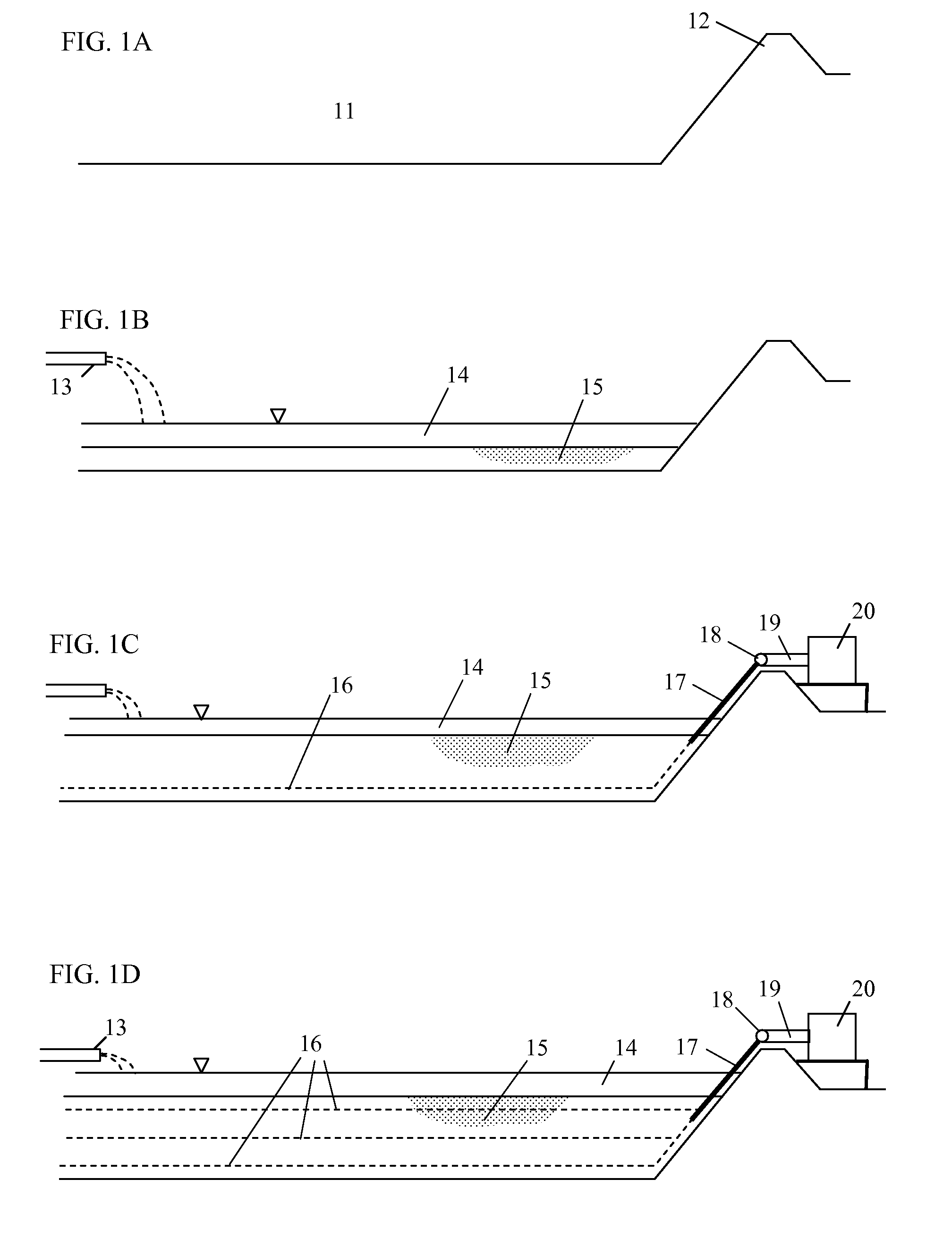
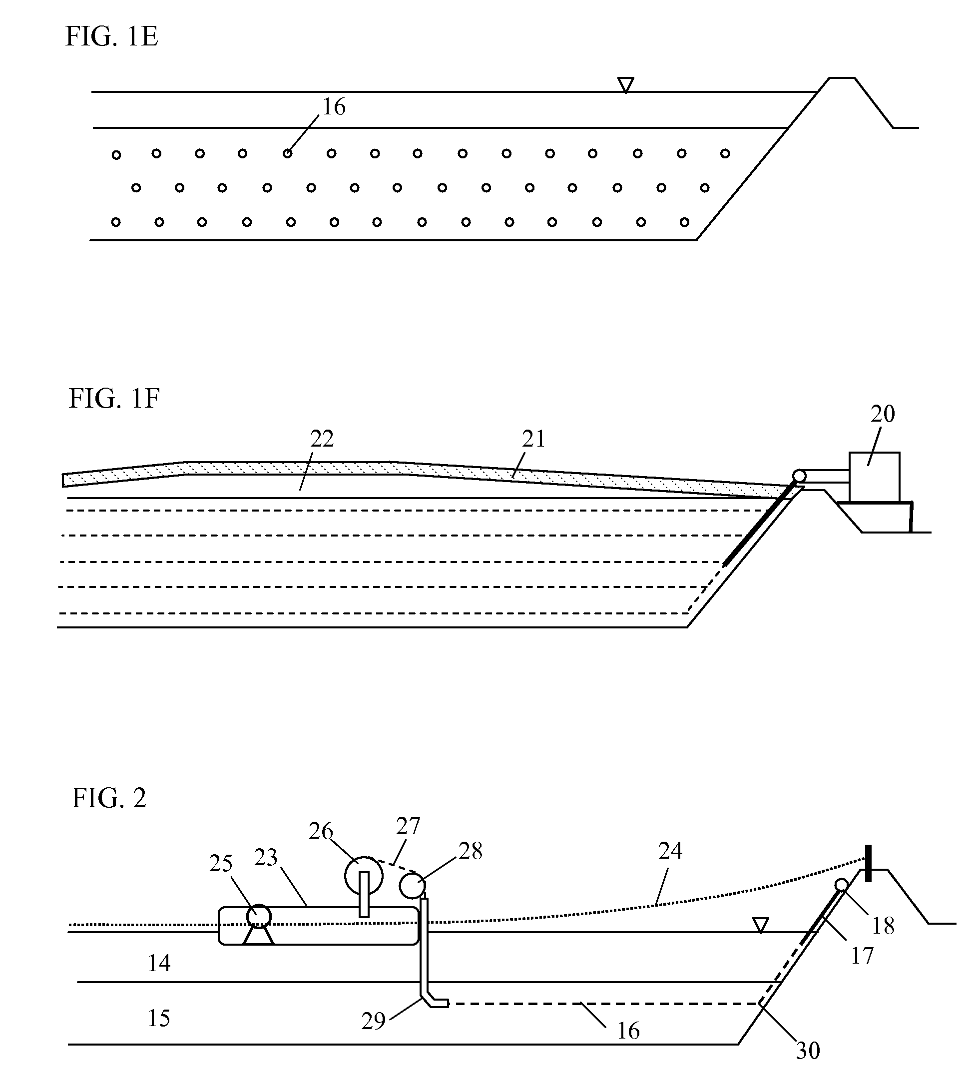
[0046]the present invention is to enhance containment performance by overconsolidation. Overconsolidation is a term referring to consolidation of soft clays under a load substantially exceeding the long-term, normal load expected at the site. In this embodiment, vacuum pump 20 is operated for several weeks to a few months after final cover installation. Then, the entire sediment in disposal pond 11 is consolidated under the combined load of final cover 21, fill 22, and vacuum pressure. As this combined load forces the entire sediment to consolidate under a more than normal load of final cover 21 and fill 22, the sediment is “overconsolidated.” The advantage of overconsolidation is obvious; the overconsolidated sediment in disposal pond 11 will no longer release water (in this case, leachate) or settle further, after vacuum loading is removed.

third embodiment

[0047]the present invention is in-situ treatment of sediment using the horizontal drains already in the sediment as a pathway to deliver liquid reagents. In general, the hardest problem with in-situ treatment of sediment is delivery of reagents uniformly into the target sediment volume. With horizontal drains embedded in the sediment volume at close, regular intervals, it is now very simple to deliver treatment reagents in a liquid form using an injection pump. Various biological, chemical or physical reagents may be used for this purpose. FIG. 4 discloses this embodiment wherein an injection pump 31 injects reagents through a set of horizontal drains 33 and an extraction pump 32 extracts reagents through another set of horizontal drains 34. Injecting clean water or a cleaning solution and extracting the same in this embodiment can flush the contaminants from the sediment for subsequent ex-situ treatment of liquid.

fourth embodiment

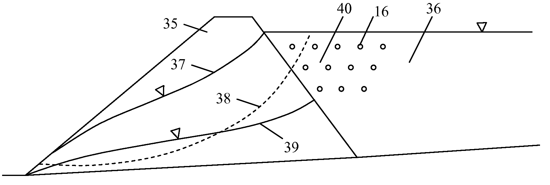
[0048]the present invention is disclosed in FIG. 5, wherein a dam 35 containing fluid earthen medium 36 is stabilized by installing horizontal drains 16 and applying vacuum consolidation using the self-sealing properties of earthen fluid medium 36. Initially, dam 35 may be unstable as a high water table 37 reduces shear resistance of soil along potential failure circle 38 and fluid earthen medium 36 in the pond exerts a high pressure on the sliding block above potential failure circle 38. Using the present invention, water level 37 in dam 35 is lowered to a lowered water table 39 and the fluid earthen medium behind dam 35 is consolidated to a stabilized earthen medium 40 having a higher shear strength. As a result, the shear resistance along potential failure circle 38 increases significantly and the dam and pond system becomes stable.


PUM

PropertyMeasurementUnit
thickaaaaaaaaaa
thickaaaaaaaaaa
thickaaaaaaaaaa

Abstract

For secure disposal of contaminated sediment, dredged sediment can be consolidated, concurrently as it is discharged to a disposal pond, using horizontal drains installed in the settled sediment and vacuum loading. Horizontal drains are connected to a vacuum pump via collector pipes and a header pipe. Vacuum pump operation consolidates the settled sediment and reduces the volume, enabling continued discharge of dredged sediment. Successive installation of horizontal drains within accumulating sediment and consolidation by vacuum pumping may continue until the disposal pond is filled with consolidated sediment. Vacuum pumping is continued for some period after final cover installation to enhance containment performance by overconsolidation. Also, the horizontal drain system may be used to deliver liquid reagents for sediment treatment or to circulate water for flushing.

Description

BACKGROUND OF THE INVENTION[0001]1. Field of Invention[0002]This invention relates to remediation of contaminated sediment by secure containment in a disposal facility and more specifically, a method of consolidating dredged sediment or fluid earthen medium in a disposal facility to reduce its volume and to stabilize its physical properties.[0003]2. Description of the Prior Art[0004]Past industrial activities have contaminated sediments in many streams, rivers, lakes, and harbors. The contaminated sediment requires remediation to mitigate its potential impact on ecological receptors, human health, or environmental media. An overview of sediment remediation options is provided below.[0005]In-situ Capping—In-situ capping isolates contaminated sediment from the surrounding surface water body or ecological receptors by placing a protective cover over the contaminated sediment area.[0006]In-Situ Treatment—In-situ treatment refers to treatment of the contaminated sediment at its current l...

Claims


Application Information

Patent Timeline
Patent Type & Authority Applications(United States)
IPC IPC(8): C02F7/00
CPCB09B1/006B09C1/08B09C1/02
Inventor HWANG, DAEKYOO
Owner HWANG DAEKYOO
Why Eureka
Try Eureka