Damping apparatus for reducing vibration of automobile body

a technology of damping apparatus and automobile body, which is applied in the direction of computer control, temperatue control, special data processing applications, etc., can solve the problems of engine vibrations increasing, the response of the actuator to command signals changing significantly, and the lack of reliability, so as to reduce the apparent natural frequency of the actuator, increase the damping characteristic, and stabilize the damping control

Active Publication Date: 2010-08-12
SHINKO ELECTRIC CO LTD
View PDF16 Cites 40 Cited by
  • Summary
  • Abstract
  • Description
  • Claims
  • Application Information

AI Technical Summary

Benefits of technology

[0027]According to the present invention, since there is provided the resonance suppression section of the actuator based on the ideal actuator inverse characteristic that uses the transfer function of the vibration velocity with respect to an excitation force of the vibrating system of the actuator, it is possible to achieve an effect where the actuator characteristic can be adjusted to an arbitrary characteristic by setting the ideal actuator inverse characteristic based on a desired characteristic. As a result, by increasing the damping characteristic of the desired characteristic, it is possible to attain a characteristic such that resonance in the movable section of the actuator is unlikely to be generated by an external force that acts on the actuator main unit. Therefore, an appropriate reaction force can be generated to thereby realize ideal vibration suppression. Moreover, since it is possible to reduce the apparent natural frequency of the actuator by reducing the natural frequency of the desired characteristic, then even in the vicinity of the natural frequency of the actual actuator, it is possible to realize stable damping control without receiving the influence of the spring characteristic and the like. Furthermore, since it is possible to maintain the movable range of the movable element of the actuator within an appropriate range, the movable element does not collide with the stopper. As a result, generation of collision sound can be

Problems solved by technology

However, the sensors need to be installed in the vicinity of the engine where they are exposed to a high temperature environment, and consequently there is a problem of a lack of reliability.
However, in controlling automobile vibration, there is a problem of negative impact on vibration suppression control in that in the case where the resonance magnification is high, if the resonance frequency changes even slightly due to temperature changes or age related changes, the response of the actuator to command signals changes significantly.
If the cylinders are stopped, there is a possibility that engine vibrations may increase compared to the vibrations in a six cylinder operation.
However, the conventional damping apparatus performs only a control to suppress vibrations being generated.
Therefore, there is a problem in that in an automobile to which control is performed to stop a predetermined number of cylinders in a six cylinder engine, all vibrations are suppressed so that it is difficult to sense that the engine is driving, and hence the driver experiences discomfort.
However, there is a problem in that since the operation of adaptive filter processing takes a long time, the damping effect is degraded if sudden changes occur in engine revolution speed, and in particular, the method realized in the frequency domain takes a long time for processing.
There is also a problem in that if there are characteristic changes or age related changes that would cause changes in the transfer function from the command values for the actuator to the signals at the measuring point (acceleration), the damping characteristic is degraded.
However, there is a problem in that individual differences or age related changes of the actuator used fo

Method used


Image

  • Damping apparatus for reducing vibration of automobile body
  • Damping apparatus for reducing vibration of automobile body
  • Damping apparatus for reducing vibration of automobile body

Examples


first embodiment

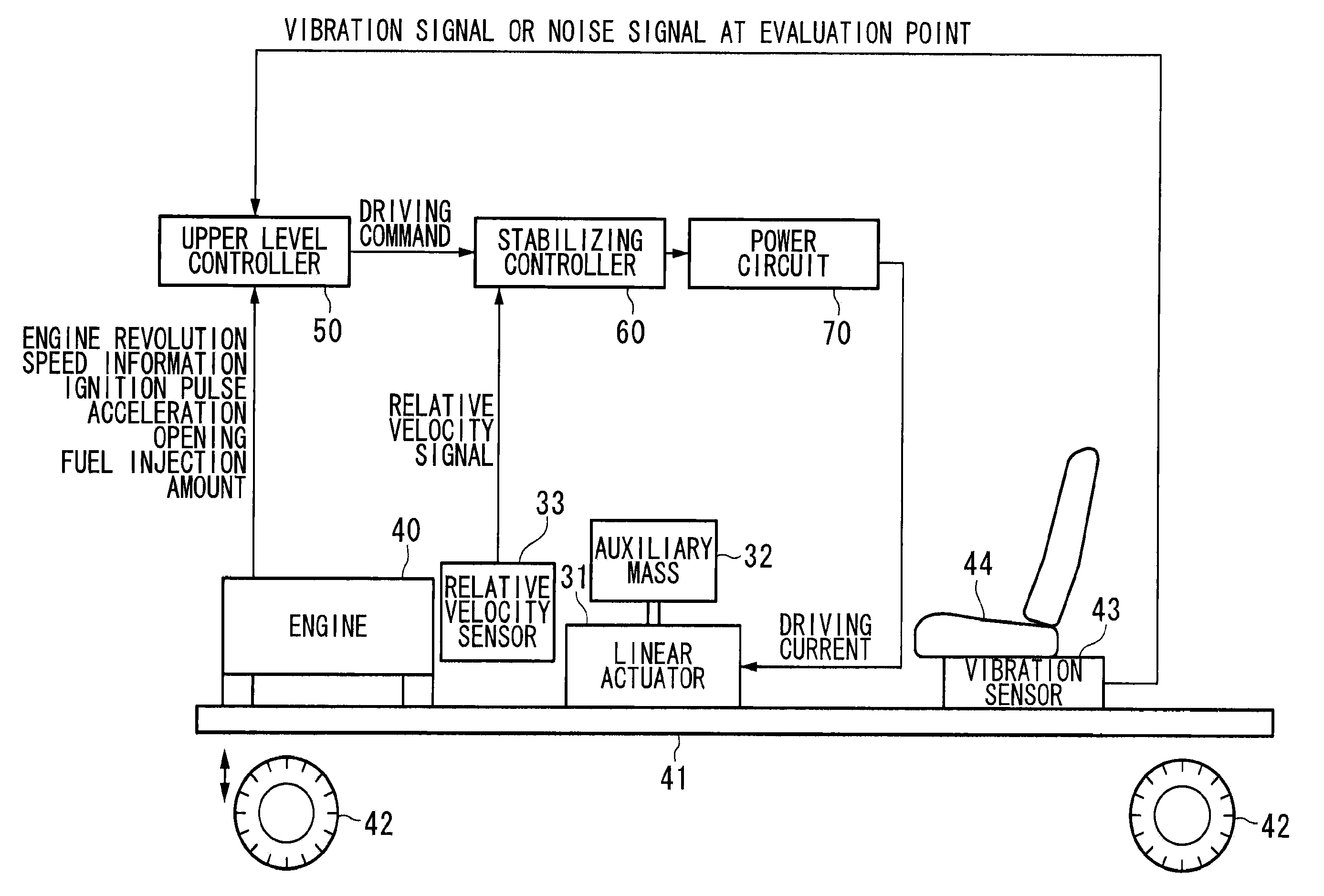
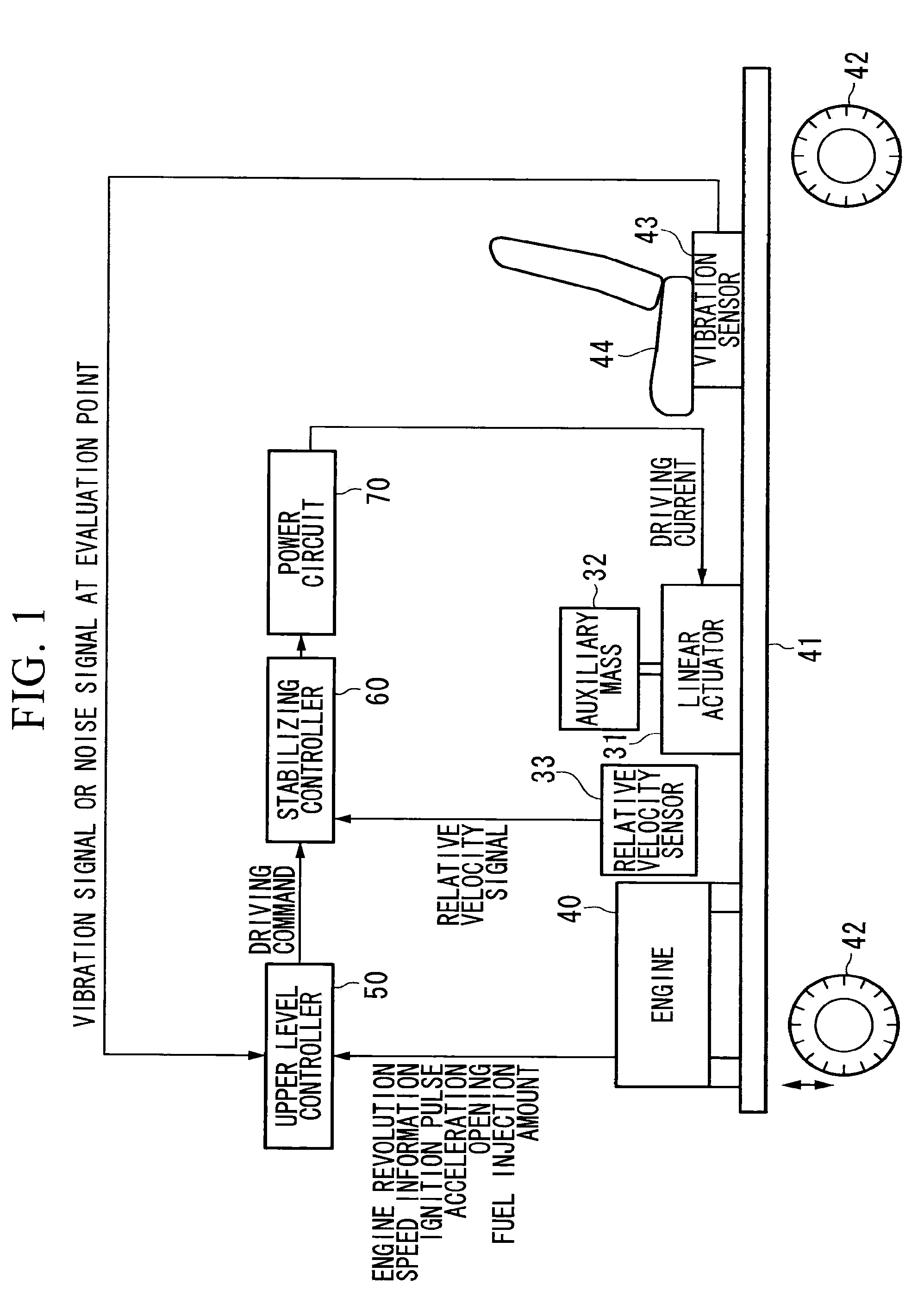
[0058]FIG. 1 is a block diagram showing a configuration of a damping apparatus according to a first embodiment of the present invention. In the present embodiment, a case is described where the damping apparatus is applied to an automobile as an example. In FIG. 1, reference symbol 31 denotes a linear actuator that reciprocates an auxiliary mass 32. The auxiliary mass 32 reciprocates in a direction the same as that of vibrations to be suppressed. Reference symbol 33 denotes a relative velocity sensor that detects a relative velocity between the linear actuator 31 and the auxiliary mass 32. Reference symbol 40 denotes an engine of an automobile that is fixed on an automobile body frame 41. Reference symbol 42 denotes wheels of the automobile. Reference symbol 43 denotes a vibration sensor (acceleration sensor) provided in a predetermined position of a passenger seat 44 or the automobile body frame 41. Reference symbol 50 denotes an upper level controller that receives input of engine...

second embodiment

[0076]Next, a configuration of a damping apparatus according to a second embodiment of the present invention is described. FIG. 3 is a block diagram showing a configuration of the damping apparatus according to the second embodiment. In FIG. 3, the damping apparatus is connected to an automobile body frame (main system mass) 41 serving as a control object, and controls (damps) vibrations in the vertical direction (gravitational direction) that occur in the body frame (main system mass) 41.

[0077]The damping apparatus in the present embodiment is a so-called active dynamic vibration absorber, and includes a current detector 63 that detects driving current to a linear actuator 31, a terminal voltage detector 64 that detects terminal voltage of the linear actuator 31, and the linear actuator 31 that drives based on detection results of the current detector 63 and the terminal voltage detector 64. The damping apparatus uses the driving force of the linear actuator 31 to drive the auxilia...

third embodiment

[0092]Next, a configuration of a damping apparatus according to a third embodiment of the present invention is described, with reference to the drawing. FIG. 10 is a block diagram showing a configuration of the same embodiment. Here, the present embodiment is described on the assumption that an engine that performs cylinder number control is an excitation source in an automobile. In this diagram, reference symbol 41 denotes an automobile body frame. Reference symbol 40 denotes an engine capable of performing cylinder number control according to the operation state thereof, and this engine 40 is a vibration generating source (excitation source). Reference symbol 44 denotes a seat of a driver's seat (hereunder, simply referred to as seat), and this seat 44 is a point at which vibrations are measured. Reference symbol 43 denotes an acceleration sensor attached to the seat 44, and this detects the acceleration of the seat 44. Reference symbol 31 denotes a linear actuator (reciprocating ...


PUM


Abstract

A damping apparatus for an automobile is provided, capable of ensuring a high level of reliability while obtaining excellent damping effect with simple configuration. The damping apparatus for an automobile that reduces vibrations of an automobile body may include an actuator that is attached to the automobile body and drives an auxiliary mass; a current detector that detects a current flowing through an armature of the actuator; a section that detects a terminal voltage applied to the actuator; a calculation circuit that calculates an induced voltage of the actuator, and further calculates at least one of the relative velocity, relative displacement, and relative acceleration of the actuator, based on a current detected by the current detector and the terminal voltage; and a control circuit that drive-controls the actuator based on at least one of the relative velocity, relative displacement, and relative acceleration of the actuator calculated by the calculation circuit.

Description

CROSS REFERENCE TO RELATED APPLICATIONS[0001]This is a U.S. national stage of application No. PCT / JP2007 / 059250, filed Apr. 27, 2007. Priority under 35 U.S.C. §119(a) and 35 U.S.C. §365(b) is claimed from Japanese Patent Application No. 2006-129013, filed May 8, 2006; Japanese Patent Application No. 2007-006006, filed Jan. 15, 2007; Japanese Patent Application No. 2007-054532, filed Mar. 5, 2007; Japanese Patent Application No. 2007-054274, filed Mar. 5, 2007; Japanese Patent Application No. 2007-055423, filed Mar. 6, 2007; and Japanese Patent Application No. 2007-105728, filed Apr. 13, 2007, the disclosures of each of which are incorporated herein by reference.TECHNICAL FIELD[0002]The present invention relates to a damping apparatus and a damping control method for an automobile for performing automobile vibration suppression control.BACKGROUND ART[0003]In order to improve riding feel and comfort of an automobile, there is a need for a contrivance so that engine vibrations are not ...

Claims


Application Information

Patent Timeline
IPC IPC(8): F16F15/00G06F19/00B60G13/16B62D37/04F16F15/02H02P25/098H02P29/00
CPCF16F7/1005F16F15/002G06F7/76B60G17/018G05D19/02
Inventor MURAGISHI, YAUSHIMORIYA, HIDEAKISATO, YUSHIFUKUNAGA, TAKASHINAKANO, KATSUYOSHINAKAGAWA, HIROSHIFUJII, TAKAYOSHIONOUE, TAKASHINARIHISA, MASAAKI
Owner SHINKO ELECTRIC CO LTD
Why Eureka
Try Eureka