

Apartment-shaped anaerobic digester for producing biogas
an anaerobic digester and apartment-shaped technology, which is applied in the direction of gas production bioreactors, feed/discharge of settling tanks, sedimentation separation, etc., can solve the problems of inability to optimally control the acid production and methanogenesis steps, inability to maintain stability, and disadvantage in terms of costs, so as to reduce the cost of production and production, inhibit growth and development, and improve the efficiency of biogas production
- Summary
- Abstract
- Description
- Claims
- Application Information
AI Technical Summary
Benefits of technology
Problems solved by technology
Method used
Image

Examples
Embodiment Construction
[0026]Features and advantages of the present invention will be more clearly understood by the following detailed description of the present preferred embodiments by reference to the accompanying drawings. It is first noted that terms or words used herein should be construed as meanings or concepts corresponding to the technical spirit of the present invention, based on the assumption that the inventor has appropriately define the concepts of the terms to best describe the present invention. Also, it should be understood that detailed descriptions of well-known functions and structures related to the present invention are not provided so as not to unnecessarily obscure the essence of the present invention.
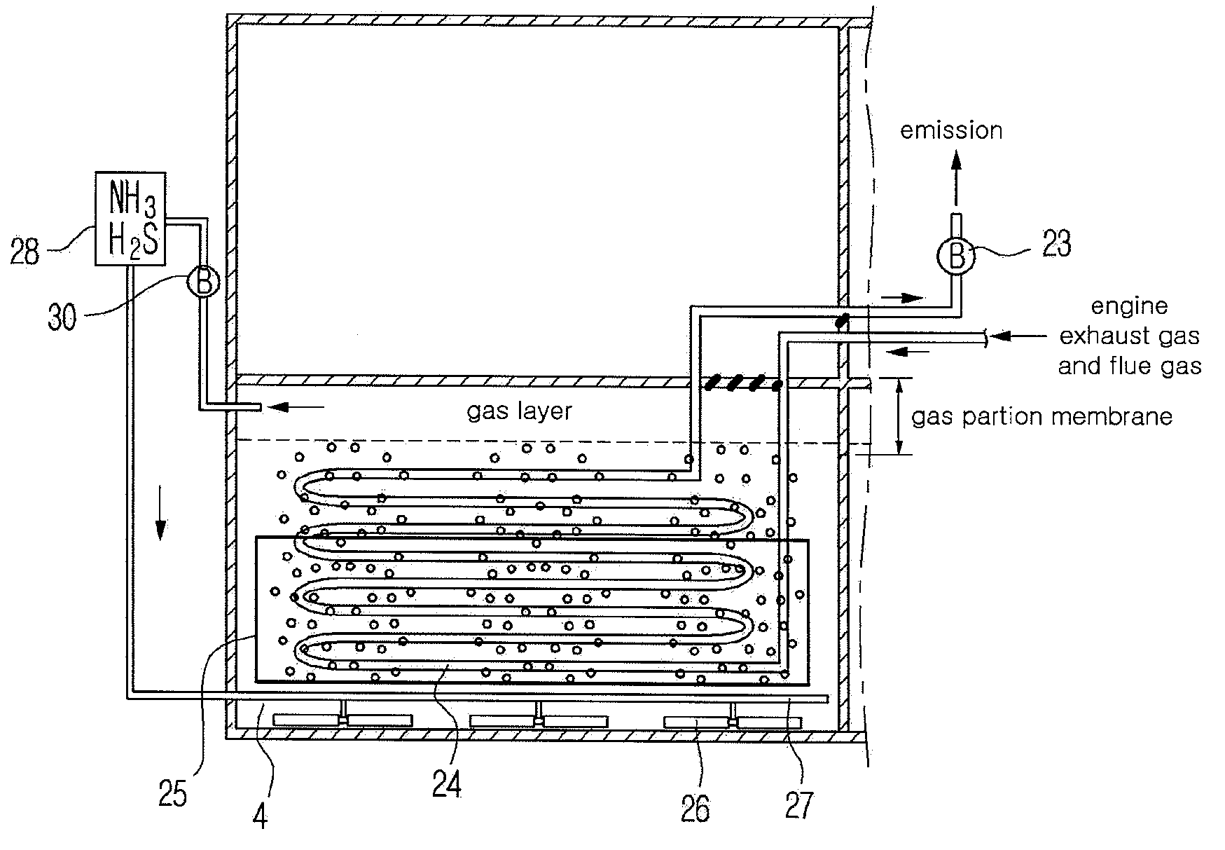
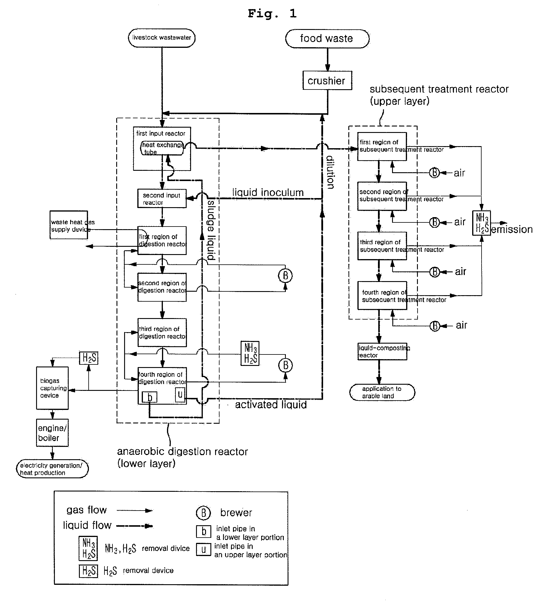
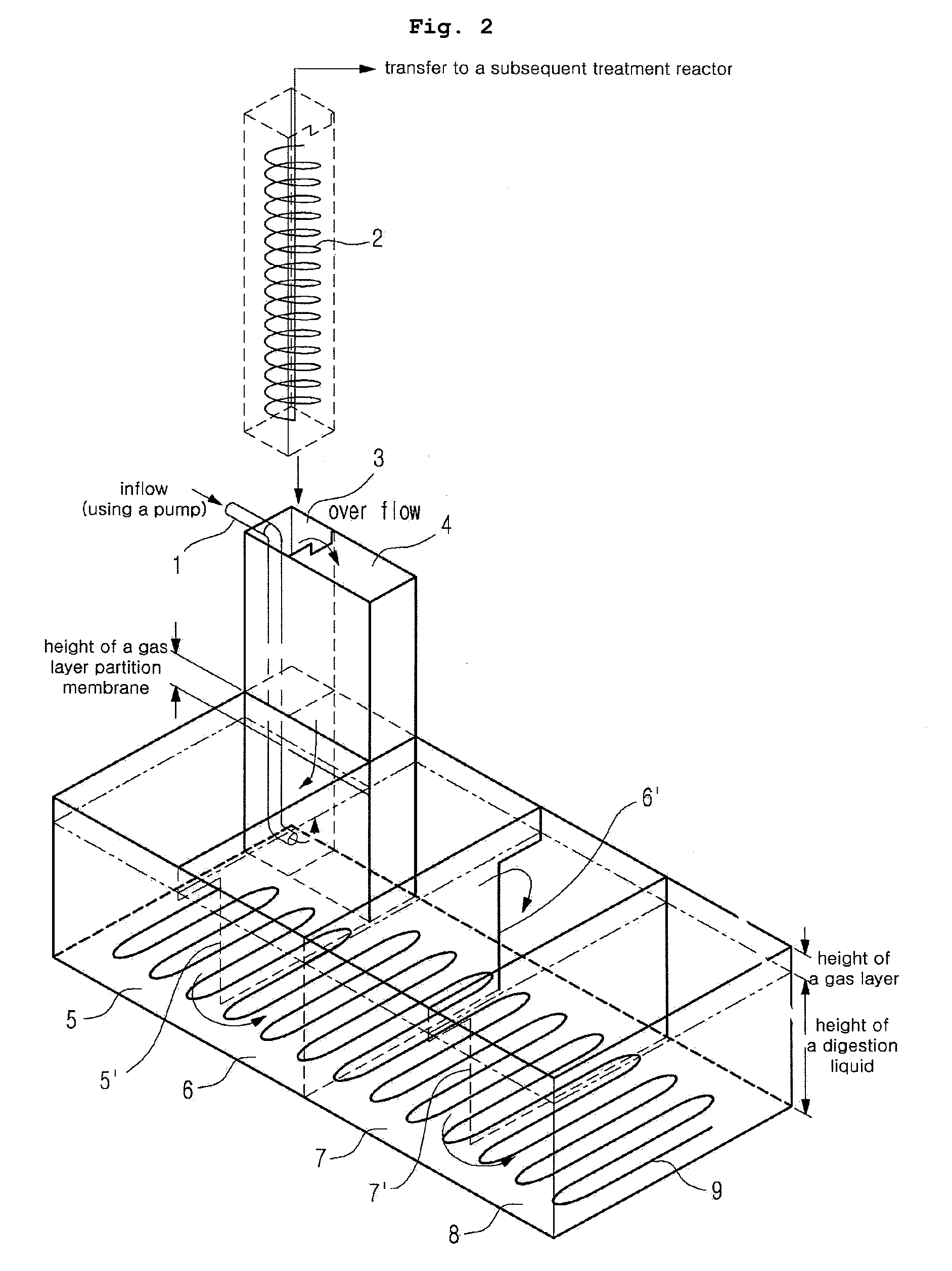
[0027]The present invention provides an apartment-shaped anaerobic digester which may increase the production efficiency of biogas by providing optimal anaerobic digestion conditions under which acid production and methanogenesis steps may be simultaneously performed in one anaerobi...
PUM
| Property | Measurement | Unit |
|---|---|---|
| temperature | aaaaa | aaaaa |
| temperature | aaaaa | aaaaa |
| temperature | aaaaa | aaaaa |
Abstract
Description
Claims
Application Information