Borehole seismic inversion in anisotropic formation

a technology of anisotropic formation and seismic inversion, which is applied in the field of simulation of acoustic properties of formations, can solve the problems of prohibitive simultaneous inversion, computational exhaustion of such elements in three-dimensional modelling, and difficult task of simulation of borehole acoustic problems, so as to achieve high computational efficiency and improve computational efficiency

Active Publication Date: 2010-08-19
TOTAL E&P DANMARK AS
View PDF33 Cites 12 Cited by
  • Summary
  • Abstract
  • Description
  • Claims
  • Application Information

AI Technical Summary

Benefits of technology

[0013]In particular, embodiments of the method disclosed herein provide a high computational efficiency by which three-dimensional wave equations are solved in cylindrical coordinates even where material anisotropy violates the conditions of axis-symmetry. The improved computational efficiency makes embodiments of the method described herein suitable for real time analysis of logging data while drilling.
[0014]Embodiments of the method described herein facilitate analysis of waves inside wellbores drilled through many different strata, each with their own orthotropic velocity characteristics, as long as the material in all layers have a principal axis in common, which to a large degree is a valid assumption for many horizontally layered sedimentary rocks. The common principal axis is generally parallel to the axis of the bore and generally vertical.

Problems solved by technology

However, the simulation of borehole acoustic problems has been found to be a difficult task, in particular because the computational simulation model used in the simulation needs to be sufficiently complex and accurate to capture the relevant physical mechanisms while remaining computationally tractable.
However, the use of such elements for three dimensional modelling becomes computationally exhaustive and prohibitive for simultaneous inversion in logging while drilling applications.

Method used


Image

  • Borehole seismic inversion in anisotropic formation
  • Borehole seismic inversion in anisotropic formation
  • Borehole seismic inversion in anisotropic formation

Examples


Embodiment Construction

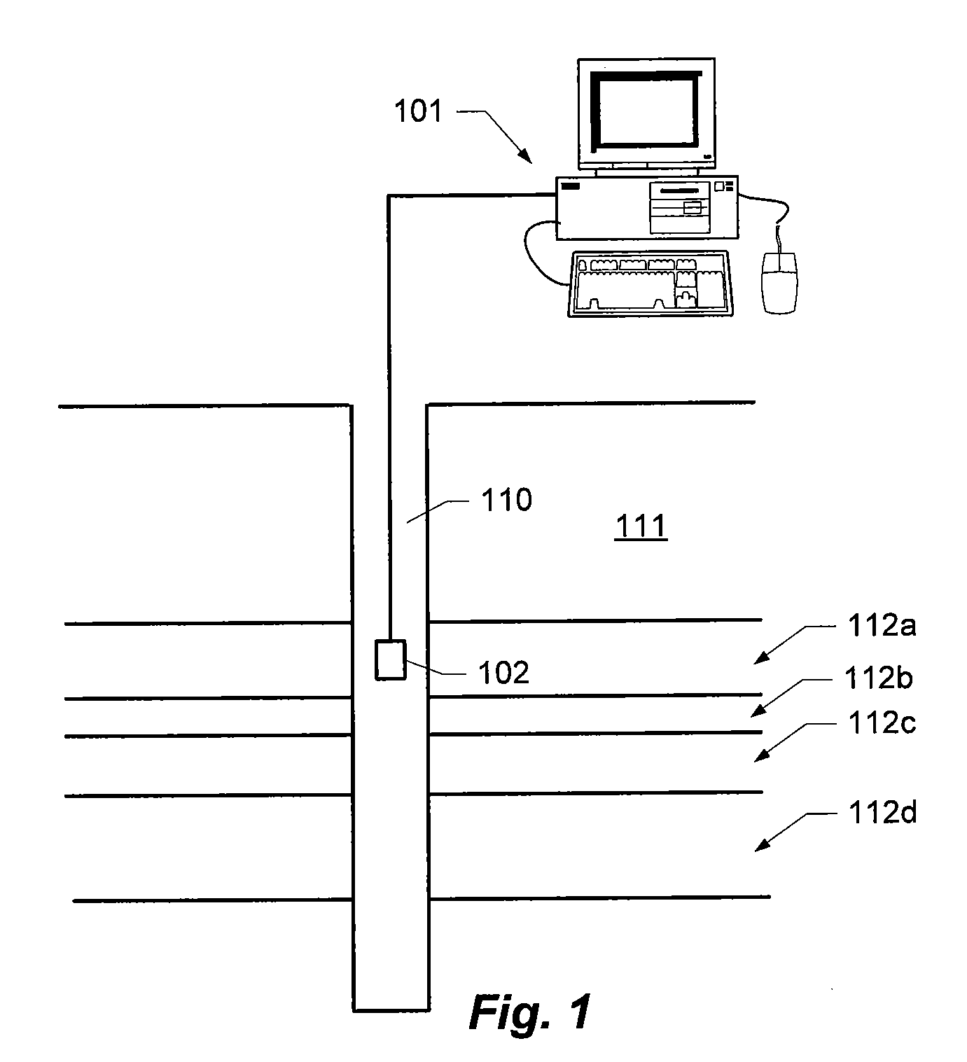
[0027]FIG. 1 shows an example of a system for performing embodiments of the method described herein. The system includes a computer 101 or other data processing system, and a sensor system 102. The computer 101 may be any suitable computer or other data processing system, e.g. a PC, a workstation, a server computer, etc. Even though illustrated as a single computer, it will be appreciated that computer 101 also may be implemented as a plurality of computers, e.g. as a client / server system including a server computer and a number of client computers connected to the client computer via a suitable computer network.

[0028]The sensor system 102 may be a sensor probe that can be inserted into a borehole e.g. suspended by a cable thus allowing for the collection of sensor measurements as a function of depth. The sensor probe may include an acoustic transmitter and an acoustic receiver for emitting an acoustic signal and for receiving a response from the surrounding formation responsive to ...


PUM


Abstract

A method of simulating a borehole acoustic response in an anisotropic formation of the crust of the earth, the method comprising: formulating a geometric model of the formation, the geometric model comprising a plurality of layers definable in a cylindrical coordinate system defined by an axial direction normal to each of the layers, a radial direction relative to the axial direction, and a circumferential direction relative to the axial direction; formulating a computational model of wave propagation in the formation, the computational model comprising one or more field variables and a wave equation describing a behaviour of the one or more field variables, wherein the one or more field variables are represented as respective Fourier series expansions of π-periodic harmonics in the circumferential direction, and numerically solving the computational model.

Description

TECHNICAL FIELD[0001]Disclosed are a method and a system for simulating acoustic properties of a formation of the crust of the earth.BACKGROUND[0002]The determination of physical properties of the formations encountered when drilling into the crust of the earth is of great interest in relation to the exploitation of hydrocarbon reservoirs or mining applications.[0003]Several techniques are known for recording physical measurements along a borehole. The results of such techniques are frequently recorded in the form of a so-called well log which provides a record of one or more physical measurements as a function of depth in a well bore.[0004]Such well logs are useful for identifying and correlating underground rocks, as well as for determining the mineralogy and physical properties of potential reservoir rocks and the nature of the fluids they contain. The process of determining the physical properties of the formation based on the measured data is generally referred to as data inver...

Claims


Application Information

Patent Timeline
Patent Type & Authority Applications(United States)
IPC IPC(8): G06F17/11G06F17/14G06G7/48
CPCG01V99/00G01V1/28G01V1/306G01V2210/67G01V2210/675
Inventor JORGENSEN, OLE
Owner TOTAL E&P DANMARK AS
Why Eureka
Try Eureka