Processless development of printing plate

a printing plate and processless technology, applied in the field of imageable lithographic plates, can solve the problems of high level of energy required for imaging such plates, low resolution, and slow rate of imaging, and achieve the effects of reducing incident dissolution, reducing the amount of lithographic plates, and improving the adhesion and cohesion of imaged areas

Inactive Publication Date: 2010-08-26
ANOCOIL
View PDF91 Cites 7 Cited by
  • Summary
  • Abstract
  • Description
  • Claims
  • Application Information

AI Technical Summary

Benefits of technology

[0019]Practitioners in this field had no reason to investigate or optimize the difference in adhesion of non-aqueous photopolymerizable resins as a basis for non-chemical, and especially mechanical, removal of the nonimage areas. Because it was the established practice that nonimage areas of the imaged plate could be substantially completely dissolved by the non aqueous developer solution, the main objective for improving coatings has been to increase the adhesion, cohesion, and durability of the imaged areas and thereby enable the plate

Problems solved by technology

Not only is a high level of energy required for imaging such pl

Method used


Image

  • Processless development of printing plate
  • Processless development of printing plate
  • Processless development of printing plate

Examples


examples

[0060]In a first trial at a commercial newspaper printing facility, a negative working, photopolymerizable plate was imaged with IR radiation at 90 mj / cm2 and developed on press during startup as described above, then used in the normal manner to print over 100,000 high quality newspaper sheets. The plate was constituted as follows:

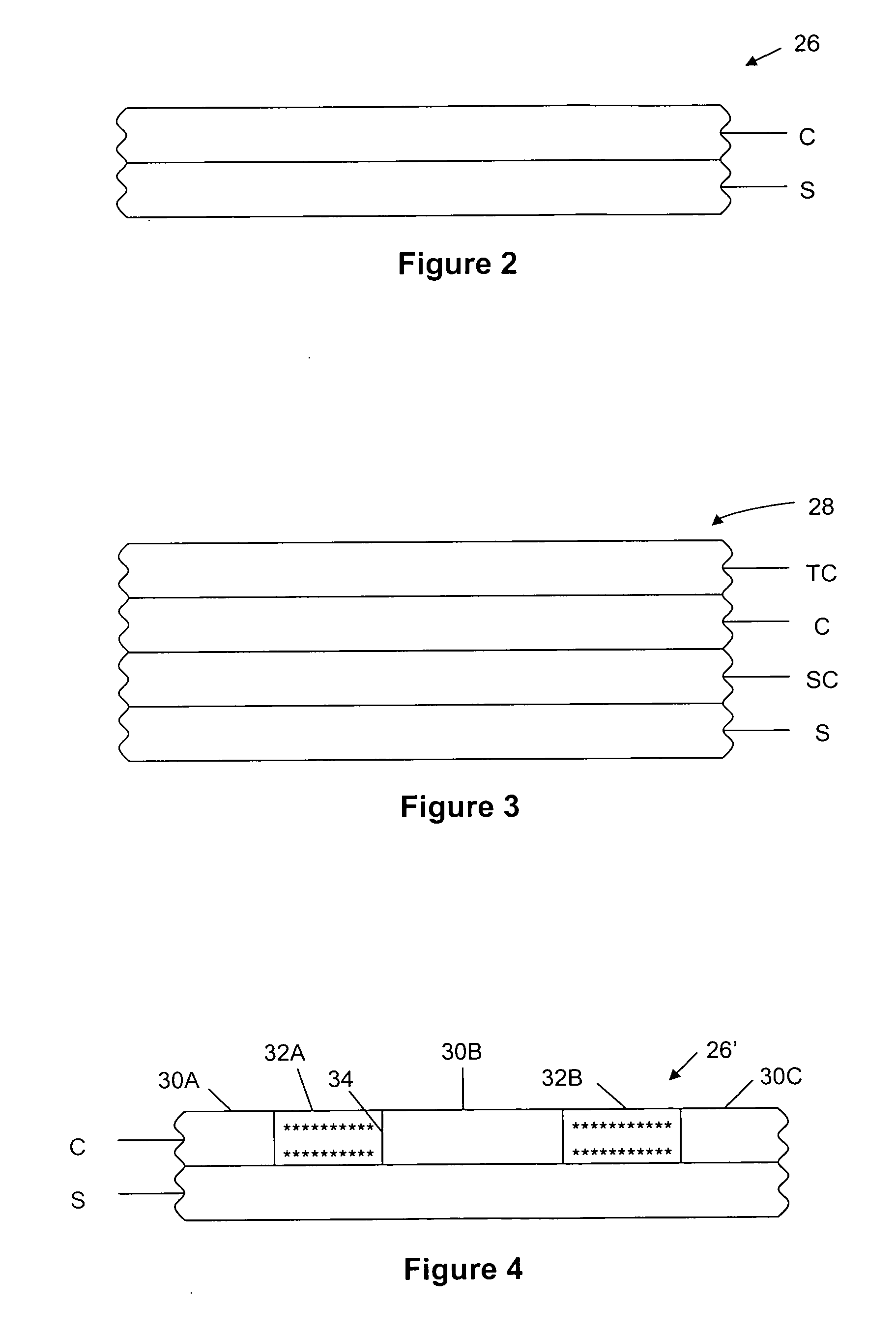
[0061](a) grained, hydrophilized aluminum substrate

[0062](b) imageable coating comprising the raw materials[0063](i) organic solvent[0064](ii) polyvinyl butyral polymer resin[0065](iii) penta functional acrylate monomer[0066](iv) pigment dispersion[0067](v) stabilizer[0068](vi) IR dye[0069](vii) organo-borate catalyst[0070](vii) onium salt catalyst[0071](viii) partially water soluble additive (DTTDA)

[0072](c) PVOH topcoat

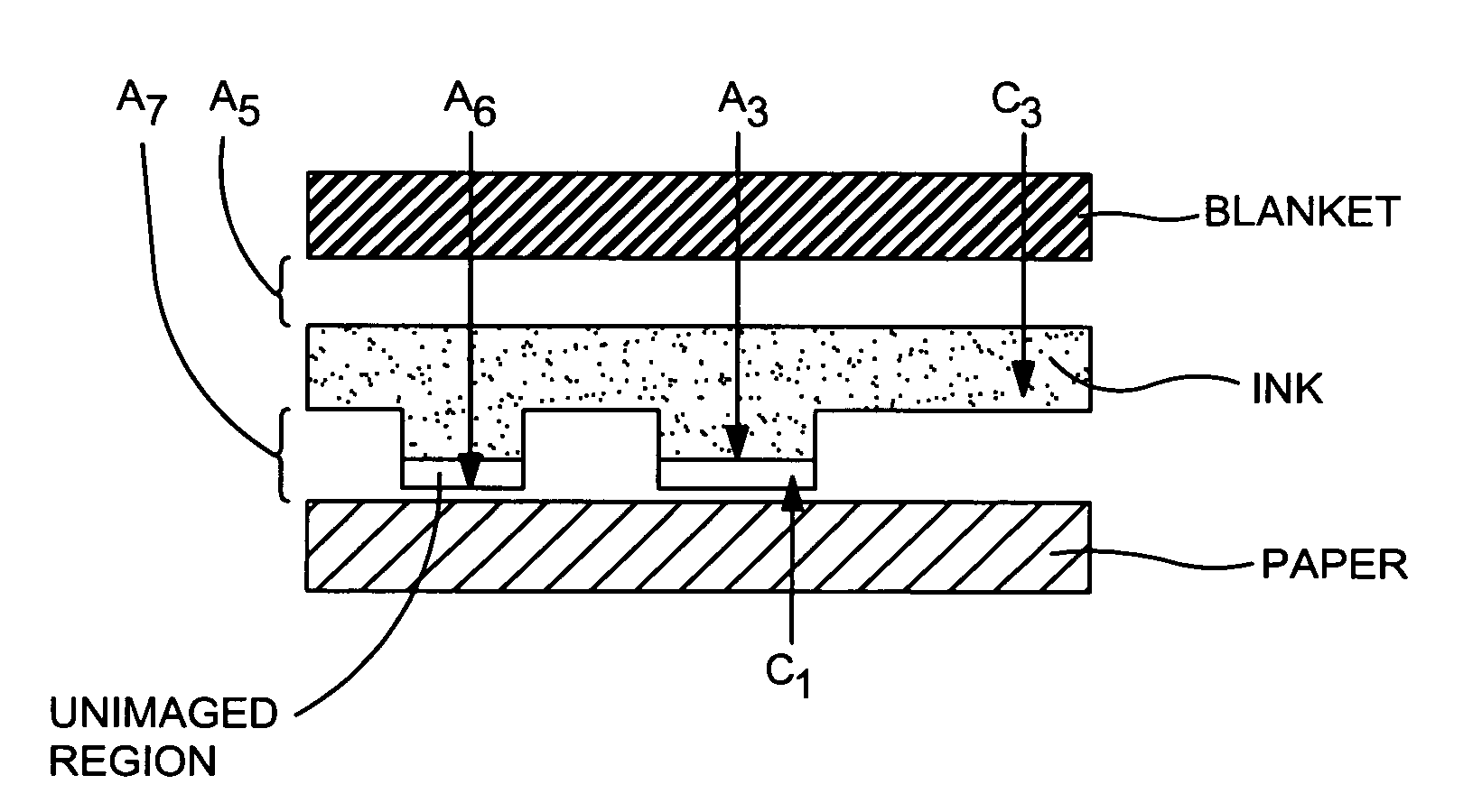
[0073]After thermal imaging, the plate was post-heated. It is believed this step produces further cross linking in the imaged areas but not in the unimaged areas. After cooling, the topcoat was washed off with tap water. Several hours aft...


PUM

PropertyMeasurementUnit
Fractionaaaaaaaaaa
Fractionaaaaaaaaaa
Fractionaaaaaaaaaa

Abstract

On-press development of an imaged printing plate on a plate cylinder, in which ink is applied by an ink form roll, a blanket roll is in contact with the plate, a rubber roll is opposed to the blanket roll, and printable media passes between the blanket roll and the rubber roll. The plate comprises a substrate carrying an imaged coating, in which nonimage areas have cohesion C1, adhesion to the substrate A1, and adhesion to the applied ink A3 and image areas have cohesion C2, adhesion to the substrate A2, and adhesion to the applied ink A4. The ink has cohesion C3 and adhesion A5 to the blanket roll. The nonimage areas have adhesion A6 to the printable medium and the ink has adhesion A7 to the medium. The adhesions and cohesions are such that the blanket roll pulls the ink from the plate and the ink pulls the nonimage areas from the substrate as undissolved particles that are transferred by the blanket with the ink to the printable media.

Description

RELATED APPLICATIONS[0001]This is a continuation-in-part of U.S. application Ser. No. 12 / 586,764 filed Sep. 28, 2009 for “Non-Chemical Development of Printing Plates”, which is a continuation-in-part of U.S. application Ser. No. 11 / 493,183 filed Jul. 26, 2006 for “Imageable Printing Plate for On-Press Development”, which claims priority under 35 U.S.C. §119(e) from U.S. Provisional Application No. 60 / 704,140 filed Jul. 29, 2005, for “Imageable Printing Plate for On-Press Development”, and benefit under 35 U.S.C. §120 is also claimed from U.S. application Ser. No. 11 / 821,721 filed Jun. 25, 2007 for “Water Spray Development of Planographic Plates” and U.S. application Ser. No. 12 / 215,124 filed Jun. 25, 2008 for “Heated Water Spray Processor”. The complete disclosures of these applications are hereby incorporated by reference.BACKGROUND OF THE INVENTION[0002]The present invention relates to imageable lithographic plates for printing.[0003]Plates of interest have a solvent-soluble, radi...

Claims


Application Information

Patent Timeline
IPC IPC(8): B41F7/02G03F7/20B05D3/12
CPCB41C1/1008B41C1/1016B41C1/1075B41C2210/24G03F7/3035B41C2210/04B41C2210/08B41C2201/02
Inventor FROMSON, HOWARD A.RYAN, WILLIAM J.ROZELL, WILLIAM J.
Owner ANOCOIL
Why Eureka
Try Eureka