

Method of manufacturing inkjet head and inkjet recording apparatus
- Summary
- Abstract
- Description
- Claims
- Application Information
AI Technical Summary
Benefits of technology
Problems solved by technology
Method used
Image

Examples
modified embodiment 1
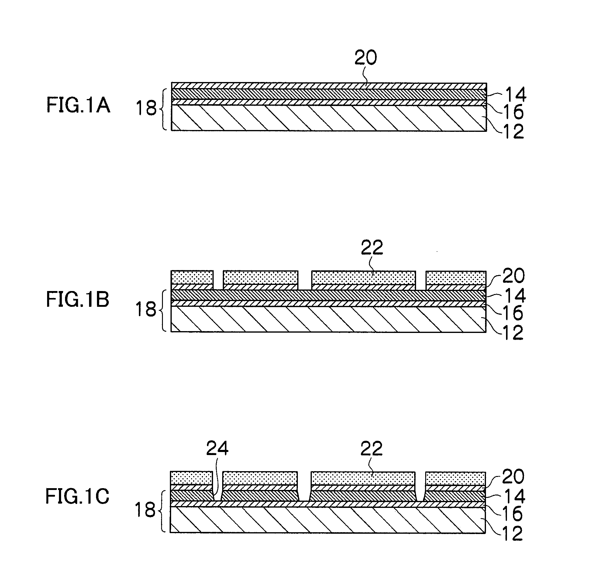
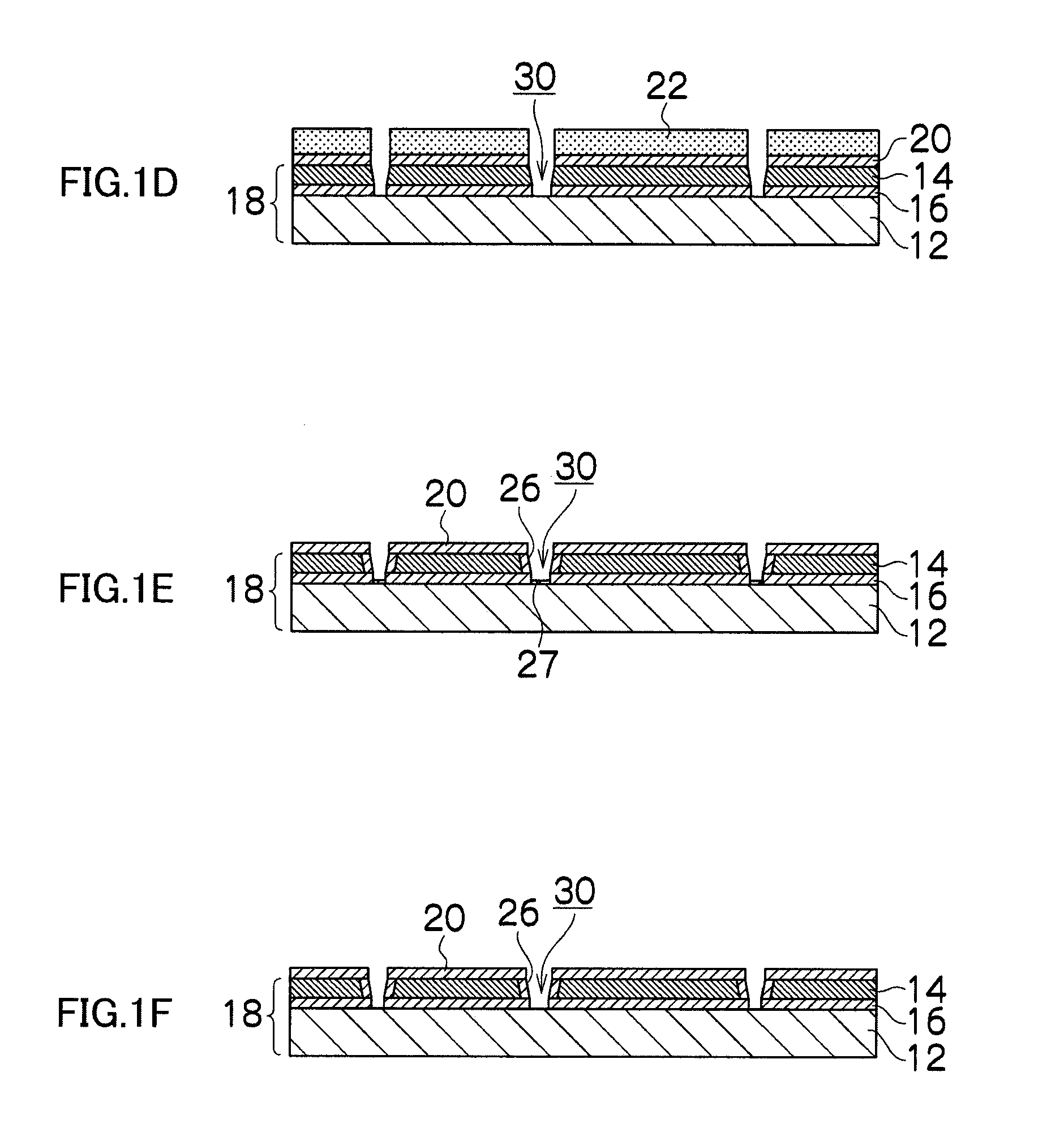
[0037]It is possible to omit the steps in FIGS. 1E and 1F for forming the thermal oxide film 26 inside the nozzles.
modified embodiment 2
[0038]It is possible to form a separate protective film, instead of the thermal oxide film 46 for protecting the flow channels formed inside the flow channels 44 of the flow channel structure body 40. Furthermore, it is also possible to adopt a mode which omits the thermal oxide film 20 described with reference to FIG. 1A.
modified embodiment 3
[0039]In FIGS. 1G to 1J, the case has been shown in which the piezoelectric elements are bonded to the flow channel structure body 40, but the present invention is not limited to this, and it is also possible to adopt modes such as a flow channel structure body in which piezoelectric elements are not bonded or a flow channel structure body to which a diaphragm is not bonded either, and a diaphragm bonding step, a piezoelectric film bonding step, an individual electrode forming step, and the like, may be carried out either before or after the step of bonding the flow channel structure to the nozzle wafer.
PUM
 Abstract
Description
Claims
Application Information