
Intake Manifold With Integrated Canister Circuit For A Supercharged Internal Combustion Engine

a technology of internal combustion engine and canister circuit, which is applied in the direction of charge feed system, non-fuel substance addition to fuel, condensed fuel collection/return, etc., can solve the problems of determining non-negligent assembly cost, relatively long assembly time, and complex canister circuit. , to achieve the effect of simple assembly and easy and cost-effective manufactur

Active Publication Date: 2010-09-02
MARELLI EURO SPA
View PDF5 Cites 12 Cited by
  • Summary
  • Abstract
  • Description
  • Claims
  • Application Information

AI Technical Summary

Benefits of technology

[0006]It is the object of the present invention to make an intake manifold with integrated canister circuit for a supercharged internal combustion engine, such an intake manifold with integrated canister circuit being free from the above-described drawbacks, being easy and cost-effective to manufacture, having a small number of components and being simple to assemble.

Problems solved by technology

Consequently, in a supercharged internal combustion engine, the canister circuit is more complex because, downstream of the canister solenoid valve, the recovery pipe has a fork adjusted by a one-way membrane valve; one branch of the recovery pipe fork leads to the intake manifold plenum, while the other branch of the recovery pipe fork leads to an intake manifold upstream of the turbocharger.
By effect of the presence of the fork in the recovery pipe and of the one-way membrane valve, the canister circuit of a supercharged internal combustion engine has various external components (tubings and pipe fittings) and is relatively complex and extended; consequently, the assembly of the canister circuit of a supercharged internal combustion engine takes a relatively long assembly time and thus determines a non-negligible assembly cost.

Method used


Image

  • Intake Manifold With Integrated Canister Circuit For A Supercharged Internal Combustion Engine
  • Intake Manifold With Integrated Canister Circuit For A Supercharged Internal Combustion Engine
  • Intake Manifold With Integrated Canister Circuit For A Supercharged Internal Combustion Engine

Examples


Embodiment Construction

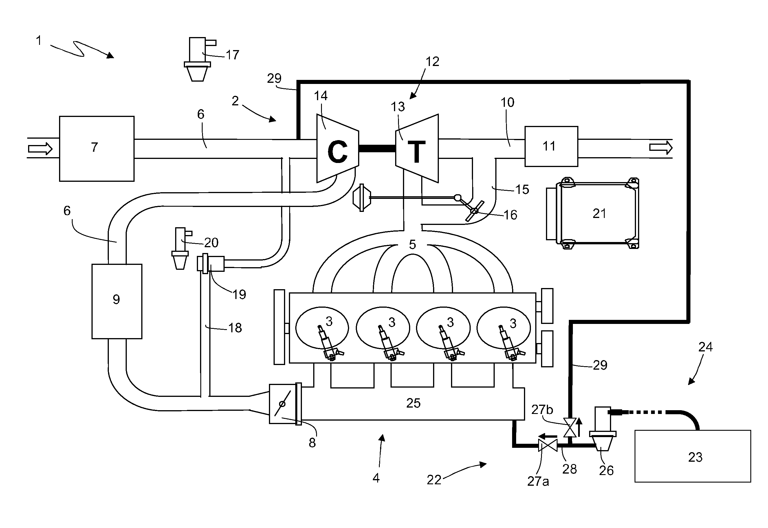
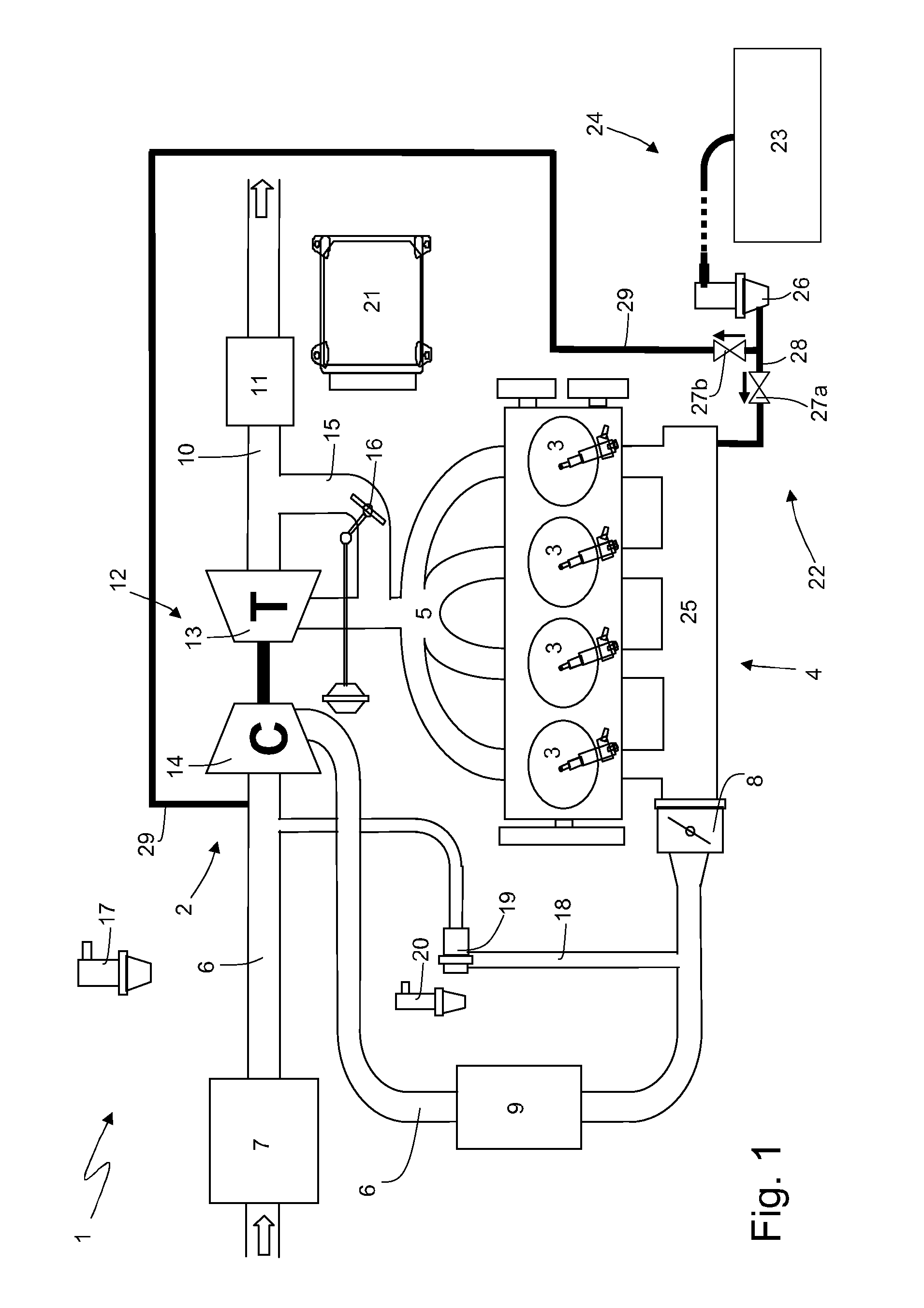
[0013]In FIG. 1, numeral 1 indicates as a whole an internal combustion engine supercharged by a turbocharger supercharging system 2.

[0014]The internal combustion engine 1 comprises four cylinders 3, each of which is connected to an intake manifold 4 by means of at least one corresponding intake valve (not shown) and to an exhaust manifold 5 by means of at least one corresponding exhaust valve (not shown). The intake manifold 4 receives fresh air (i.e. air coming from the external environment) through an intake pipe 6, which is provided with an air filter 7 and is adjusted by a butterfly valve 8. An intercooler 9 for cooling the aspirated air is arranged along the intake pipe 6. To the exhaust manifold 5 there is connected an exhaust pipe 10 which feeds the exhaust gases produced by the combustion to an exhaust system, which emits the gases produced by the combustion into the atmosphere and normally comprises at least one catalyzer 11 and at least one muffler (not shown) arranged dow...


PUM


Abstract

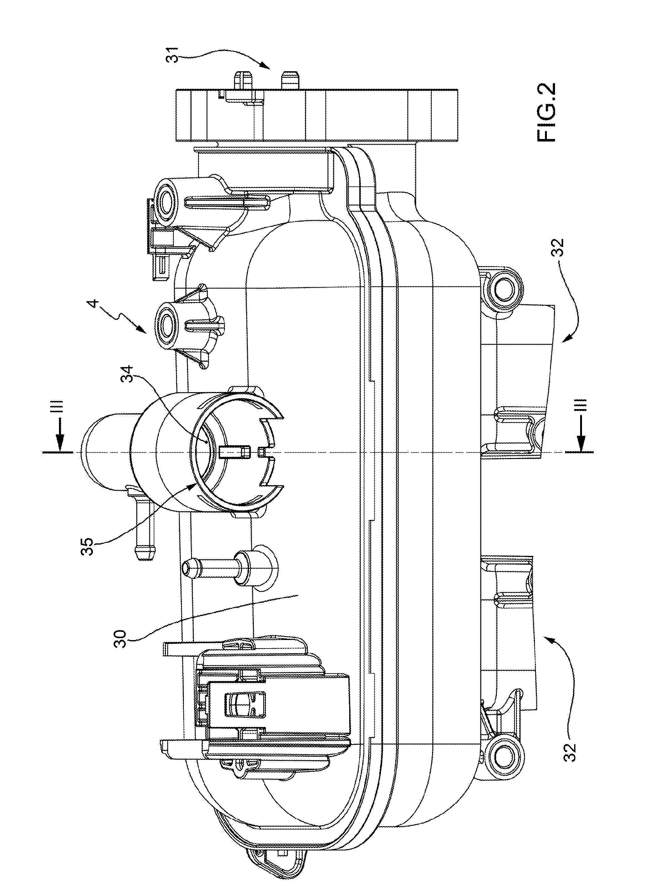
An intake manifold with integrated canister circuit for a supercharged internal combustion engine; the intake manifold is provided with: a tubular body in which a plenum is defined; a sorting chamber, which is obtained in a wall of the tubular body; a canister solenoid valve, which is arranged in the sorting chamber and is adapted to adjust the introduction of gasoline vapours into the sorting chamber itself; a first pipe, which is obtained in the wall of the tubular body, puts the sorting chamber into communication with the plenum, and defines a first branch of a recovery pipe; a second pipe, which is obtained in the wall of the tubular body and defines an initial portion of a second branch of the recovery pipe; a first one-way valve which is arranged in the sorting chamber in correspondence of the first pipe and allows, through the first pipe, only a flow towards the plenum; a second one-way valve which is arranged in the sorting chamber in correspondence of the second pipe and allows, through the second pipe, only a flow through the intake pipe.

Description

TECHNICAL FIELD[0001]The present invention relates to an intake manifold with integrated canister circuit for a supercharged internal combustion engine.BACKGROUND ART[0002]An internal combustion engine is provided with a canister circuit, which has the function of recovering the fuel vapours which are produced in the fuel tank and of introducing such fuel vapours into the cylinders in order to be burnt; this prevents the fuel vapours which are produced in the fuel tank from leaking from the fuel tank (specifically when the fuel filler cap is opened for refueling) and being freely dispersed into the atmosphere.[0003]In an aspirated internal combustion engine (i.e. without supercharging), the canister circuit comprises a recovery pipe which originates in the fuel tank and ends in the intake manifold plenum and is adjusted by a canister solenoid valve of the on / off type. Atmospheric pressure is essentially present inside the fuel tank, while a slight vacuum is present in the intake man...

Claims


Application Information

Patent Timeline
IPC IPC(8): F02M33/02F02B33/00F02M35/10
CPCF02M25/08F02M25/0836F02M35/10144F02M35/112F02M35/10222F02M35/10288F02M35/10157
Inventor FORNARA, STEFANODAVITTI, ANDREAPECORA, MICHELE
Owner MARELLI EURO SPA
Learn More