Heat transfer controlling mechanism and fuel cell system having the heat transfer controlling mechanism

a technology of heat transfer control and fuel cell system, which is applied in the direction of process control, lighting and heating apparatus, instruments, etc., can solve the problems of unable to supply sufficient energy through the primary battery without increasing the size and weight of the device, and unable to allow the secondary battery to be immediately used on demand, etc., to achieve efficient heat transfer and reduce the effect of size and power consumption

Inactive Publication Date: 2010-09-02
CANON KK
View PDF6 Cites 37 Cited by
  • Summary
  • Abstract
  • Description
  • Claims
  • Application Information

AI Technical Summary

Benefits of technology

[0062]The present invention is directed to a heat transfer controlling mechanism that permits a working fluid to flow in a predetermined direction in a loop-shaped flow path without causing a back flow using a simple structure, which is not restricted to the orientation in a use state, and which has low power consumption and can realize efficient heat transfer and size reduction.
[0063]Moreover, the present invention is directed to a fuel cell system, which has the heat transfer controlling mechanism of the present invention mounted thereon to thereby have the ability, in addition to the function of the heat transfer controlling mechanism, to maintain the fuel cell power generation unit and the fuel tank at suitable temperatures.
[0082]According to the present invention, it is possible to realize a heat transfer controlling mechanism, which allows a working fluid to flow in a predetermined direction in a loop-shaped flow path without causing back flow with a simple structure. There is no restriction on the orientation of this mechanism during use. This mechanism has low power consumption and can provide an efficient heat transfer and size reduction. Further, by mounting the heat transfer controlling mechanism of the present invention, a fuel cell system can be realized, which, in addition to the functions of the heat transfer controlling mechanism, can maintain the fuel cell power generation unit and the fuel tank at suitable temperatures.

Problems solved by technology

However, with the recent development of high-performance small-sized electric devices, power consumption has become large, so that sufficient energy cannot be supplied by means of a primary battery without increasing the size and weight of the devices.
In addition, it generally takes from several tens of minutes to several hours to charge a secondary battery, so that it is difficult to allow the secondary battery to be immediately used on demand.
In the future, with the increase in the tendency of carrying and using electric devices, a further reduction in their size and weight, and implementation of wireless network environments, it is difficult for conventional primary and secondary batteries to supply a sufficient amount of energy to drive such devices.
However, hydrogen is gaseous at ordinary temperature, and it has been difficult to store hydrogen at a high density in a small fuel tank.
However, the polymer electrolyte membrane has such a property that when the temperature exceeds 100° C., the power generation performance is remarkably decreased.
Generally, in the fuel cell stack, there is a tendency in that as a cell is positioned closer to the central part, its radiation efficiency becomes poor and its temperature becomes high, and as a cell is positioned closer to the end part, its temperature becomes low.
However, the above-mentioned conventional examples of the loop heat pipe have problems as described below.
However, when such a fluid machine is provided, the system becomes complicated and large, and the power consumption is increased, which results in disadvantages in achieving a reduction of the size of the system.
However, because gravity is utilized to reflux the condensed fluid, there is a possibility that if the heat pipe is reduced in size so that the influence of a frictional force becomes large, or if the heat pipe is incorporated into a device the vertical direction of which is not determined, the heat pipe would not effectively operate.
However, this valve is opened / closed by the temperature of working vapor and cannot be controlled according to the temperature conditions of the outside of the pipe.
However, a mechanism for preventing the back flow is not incorporated.
In addition, the quantity of transported heat cannot be controlled.
Further, the above-mentioned examples of the conventional fuel cell system have problems as described below.
For example, the fuel cell of Japanese Patent Application Laid-Open No. 2004-31096 can prevent the temperature elevation of the fuel cell, but does not effectively function with respect to lowering the temperature inside the fuel tank.
Furthermore, since a heat transfer is performed mainly by heat conduction in a solid, when a large amount of heat is generated, or when the heat transport distance is large, there is a possibility that the ability to transport heat may become insufficient.
H06-260202 and H10-064567, when heat exchange is performed between the fuel cell unit and the fuel tank, a circulating device for cooling water or exhaust gas is required, which may result in a size increase of the system and a decrease in the energy utilization efficiency of the entire system.
The fuel cell disclosed in U.S. Pat. No. 6,268,077 does not require a special system for heat exchange, but the heat exchange amount is determined by the area of the fuel cell principal surface so that it is difficult to optimally control the heat exchange quantity depending on the temperature.
Accordingly, when such a linear heat pipe utilizing gravity while being directed downward is used for a fuel cell the vertical direction of which at the time of use is not determined, there is a possibility that the heat pipe may not effectively operate.

Method used


Image

  • Heat transfer controlling mechanism and fuel cell system having the heat transfer controlling mechanism
  • Heat transfer controlling mechanism and fuel cell system having the heat transfer controlling mechanism
  • Heat transfer controlling mechanism and fuel cell system having the heat transfer controlling mechanism

Examples


embodiment 1

[0124]The configuration of a loop heat pipe of Embodiment 1 of the present invention will be described.

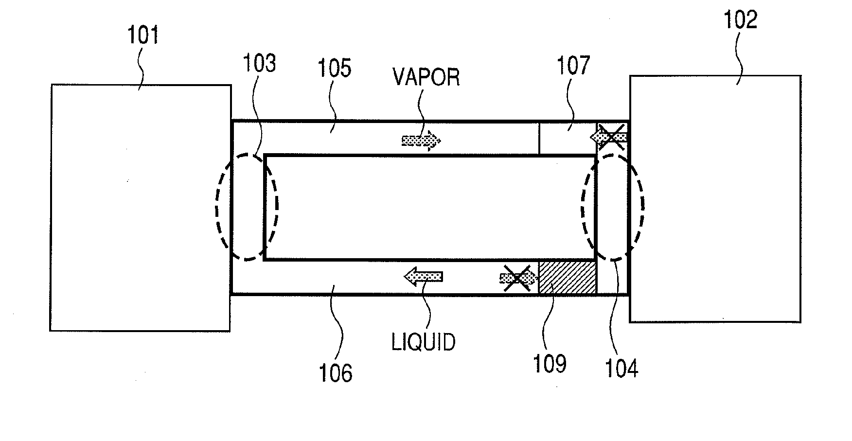
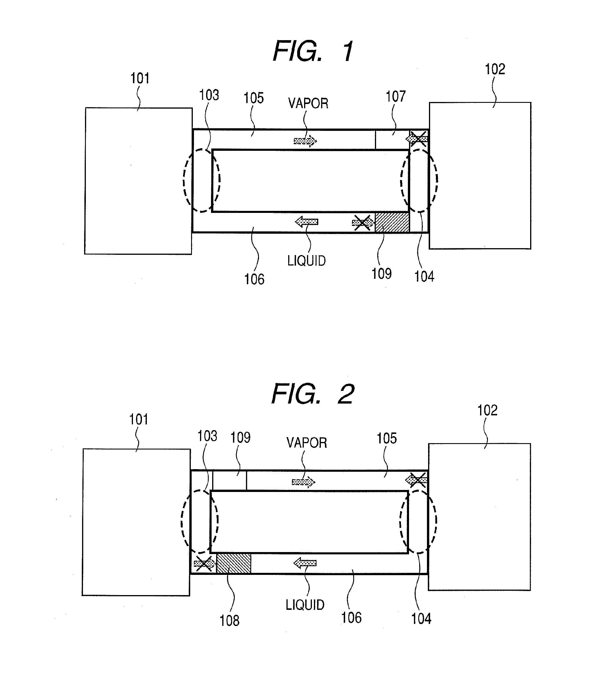
[0125]FIG. 1 is a schematic diagram illustrating the configuration of the loop heat pipe of Embodiment 1. In FIG. 1, reference numeral 101 denotes a high temperature portion, 102 a low temperature portion, 103 a vaporizing portion, 104 a condensing portion, 105 a vapor flow path, 106 a liquid flow path, 107 a hydrophobic portion, and 109 a wettability changing portion. In the loop heat pipe of this embodiment, the vaporizing portion 103 is provided in contact with the high temperature portion 101, the condensing portion 104 is provided in contact with the low temperature portion, and a loop-shaped flow path is provided between the vaporizing portion 103 and the condensing portion 104.

[0126]One side of the loop-shaped flow path is the vapor flow path 105, and the other side thereof is the liquid flow path 106. The vapor flow path 105 is provided with a portion, which permits the pas...

embodiment 2

[0146]The configuration of a loop heat pipe of Embodiment 2 of the present invention will be described.

[0147]FIG. 7 is a schematic diagram illustrating the configuration of the loop heat pipe of Embodiment 2. In FIG. 7, the elements that are the same as those described in Embodiment 1 are identified by like numerals, so that the description of common portions will be omitted.

[0148]In FIG. 7, reference numeral 108 denotes a hydrophilic portion, and reference numeral 201 denotes a member, which is displaced depending on temperature.

[0149]In the loop heat pipe of this embodiment, a vaporizing portion 103 is provided in contact with the high temperature portion 101, a condensing portion 104 is provided in contact with the lower temperature portion 102, and a loop-shaped flow path is provided between the vaporizing portion 103 and the condensing portion 104.

[0150]One side of the loop-shaped flow path is a vapor flow path 105, and the other side is a liquid flow path 106. The vapor flow p...

example 1

[0162]In Example 1, a first production method of a loop heat pipe of Embodiment 1 will be described.

[0163]Although in this example description will be made by taking as an example a case where the semiconductor processing technology is mainly used, the heat pipe may be produced by using the mechanical processing technology, such as cutting or pressing.

[0164]FIGS. 9A to 9E are views illustrating a first production method of producing a loop-type heat pump of Embodiment 1.

[0165]In FIGS. 9A to 9E, the elements that are the same as those described in Embodiment 1 with reference to FIG. 1 are identified by like numerals, so that the description of common portions will be omitted.

[0166]In FIGS. 9A to 9E, reference numeral 301 denotes a substrate-1, 302 a substrate-2, 304 an injection port, 305 a porous portion, 306 a working fluid, and 307 a sealing agent.

[0167]In the production method of the loop heat pipe of this example, FIG. 9A shows a step of forming flow paths 105, 106 in the substr...


PUM

PropertyMeasurementUnit
temperatureaaaaaaaaaa
voltageaaaaaaaaaa

Abstract

A heat transfer controlling mechanism and a fuel cell system, which allow working fluid to flow in a predetermined direction in a loop-shaped flow path without a back flow, having a simple structure independent of the orientation during use, low power consumption, and efficient heat transfer and size reduction. The mechanism includes a vaporizing portion, a condensing portion, and a loop-shaped flow path connecting the vaporizing and the condensing portions so as to seal working fluid. The mechanism transports heat by vaporizing the fluid in the vaporizing portion and condensing the fluid in the condensing portion to control heat transfer. The mechanism further includes a gas passage suppressing portion on one side in the flow path, for allowing liquid, but not gas, to pass therethrough and a liquid passage suppressing portion on the other side in the flow path, for allowing gas, but not liquid, to pass therethrough.

Description

TECHNICAL FIELD[0001]The present invention relates to a heat transfer controlling mechanism and a fuel cell system having the heat transfer controlling mechanism mounted thereon. More particularly, it relates to a heat transfer controlling mechanism including a loop heat pipe for allowing a working fluid to flow in a predetermined direction and for controlling the heat transfer amount thereof according to circumstances.BACKGROUND ART[0002]A heat pipe has been known as a mechanism in which a working fluid is sealed within a closed space and highly efficient heat transfer is performed by using the vaporization and condensation thereof.[0003]In the heat pipe, a working fluid, which has received heat, is vaporized at a vaporizing portion, moves within a tubular path, and is then cooled at a condensing portion to thereby return to a liquid state. The condensed working fluid is again transported to the vaporizing portion (reflux or reflow).[0004]There are many cases where the heat transpo...

Claims


Application Information

Patent Timeline
Patent Type & Authority Applications(United States)
IPC IPC(8): H01M8/04F28D15/00
CPCF28D15/0266F28D15/043F28F2245/02F28F2245/04F28D15/06H01M8/04074H01M8/04208Y02E60/50H01M8/04007
Inventor NAKAKUBO, TORU
Owner CANON KK
Why Eureka
Try Eureka