
Variable valve timing apparatus and control method therefor

Active Publication Date: 2010-09-02
TOYOTA JIDOSHA KK +1
View PDF11 Cites 3 Cited by
  • Summary
  • Abstract
  • Description
  • Claims
  • Application Information

AI Technical Summary

Benefits of technology

[0006]An object of the present invention is to provide a variable valve timing apparatus and the like, which can maintain the phase by stopping power supply to an actuator and can vary an opening / closing timing over a wide range.
[0008]According to the present invention, in the case where the opening / closing timing is in the first region, the opening / closing timing is changed at the first variation amount with respect to the operation amount of the actuator. In the case where the opening / closing timing is in the second region, the opening / closing timing is changed at the second variation amount larger than the first variation amount with respect to the operation amount of the actuator. Accordingly, the opening / closing timing can be varied widely in the second region. On the other hand, in the first region, the variation amount of the opening / closing timing is small. In other words, the reduction gear ratio is high. Therefore, for example the variation of the opening / closing timing can be restrained which is caused by driving of the actuator by the torque acting on the camshaft as the engine is operated, even in the state where the actuator generates no torque. Thus, in the first region, power supply to the actuator is stopped thereby to maintain the opening / closing timing. Therefore, it is possible to provide a variable valve timing apparatus capable of maintaining the opening / closing timing by stopping power supply to the actuator and of varying the opening / closing timing over a wide range.
[0010]According to the present invention, in the case where the opening / closing timing is in the third region, the opening / closing timing is changed such that the ratio between the operation amount of the actuator and the variation amount of the opening / closing timing, namely the reduction gear ratio is varied. For example, in the region between the first region and the second region, the reduction gear ratio is varied. Accordingly, in the case where the opening / closing timing is varied from the first region to the second region or from the second region to the first region, the variation amount of the opening / closing timing with respect to the operation amount of the actuator can be increased or decreased gradually. Therefore, a sudden stepwise change of the variation amount of the opening / closing timing can be restrained to thereby restrain a sudden change in opening / closing timing. However, in such a third region, it is difficult to predict the variation amount of the opening / closing timing with respect to the operation amount of actuator, and therefore the controllability may be deteriorated thereby to deteriorate the accuracy of the opening / closing timing. Therefore, the target timing of the opening / closing timing is set in a region other than the third region, among the first region, the second region and the third region, and then the opening / closing timing is controlled such that this target timing is achieved. Accordingly, the opening / closing timing can be set as the timing in at least any one of the first region and the second region. Therefore, the deteriorated controllability of the opening / closing timing can be restrained and the deteriorated accuracy in opening / closing timing can be restrained.
[0012]According to the present invention, in the region that is retarded, the power supply to the actuator is stopped thereby to maintain the opening / closing timing. Accordingly, for example in an engine in which the opening / closing timing is more frequently set in the retarded region, the frequency of stopping power supply to the actuator can be increased. Therefore, fuel economy can ultimately be enhanced.
[0014]According to the present invention, if the rotational speed of the internal combustion engine, namely the rotational speed of the output shaft of the internal combustion engine is lower than a predetermined rotational speed, power supply to the actuator is stopped thereby to maintain the opening / closing timing. If the rotational speed of the internal combustion engine is higher than the predetermined rotational speed, power supply to the actuator is provided thereby to maintain the opening / closing timing. Accordingly, power supply to the actuator can be stopped in the case where the opening / closing timing can be maintained even without supplying power to the actuator because of small torque acting on the camshaft which is caused by driving of the internal combustion engine. The opening / closing timing can be maintained accurately by supplying power to the actuator in the case where the opening / closing timing may be varied because of large torque acting on the camshaft which is caused by driving of the internal combustion engine.
[0016]According to the present invention, if the rotational speed of the internal combustion engine, namely the rotational speed of the output shaft of the internal combustion engine is lower than a predetermined rotational speed, power supply to the actuator is stopped thereby to maintain the opening / closing timing at the most retarded timing in the first region. If the rotational speed of the internal combustion engine is higher than the predetermined rotational speed, power supply to the actuator is provided thereby to maintain the opening / closing timing at the most retarded timing in the first region. Accordingly, power supply to the actuator can be stopped in the case where the opening / closing timing can be maintained at the most retarded timing even without supplying power to the actuator because of small torque acting on the camshaft which is caused by driving of the internal combustion engine. The opening / closing timing can be maintained accurately at the delayed timing by supplying power to the actuator in the case where the opening / closing timing may be varied because of large torque acting on the camshaft which is caused by driving of the internal combustion engine.

Problems solved by technology

Particularly, in the case where the electric motor is used to rotate the camshaft, the torque for rotating the camshaft is difficult to obtain, as compared with the case where the camshaft is hydraulically rotated.

Method used


Image

  • Variable valve timing apparatus and control method therefor
  • Variable valve timing apparatus and control method therefor
  • Variable valve timing apparatus and control method therefor

Examples


first embodiment

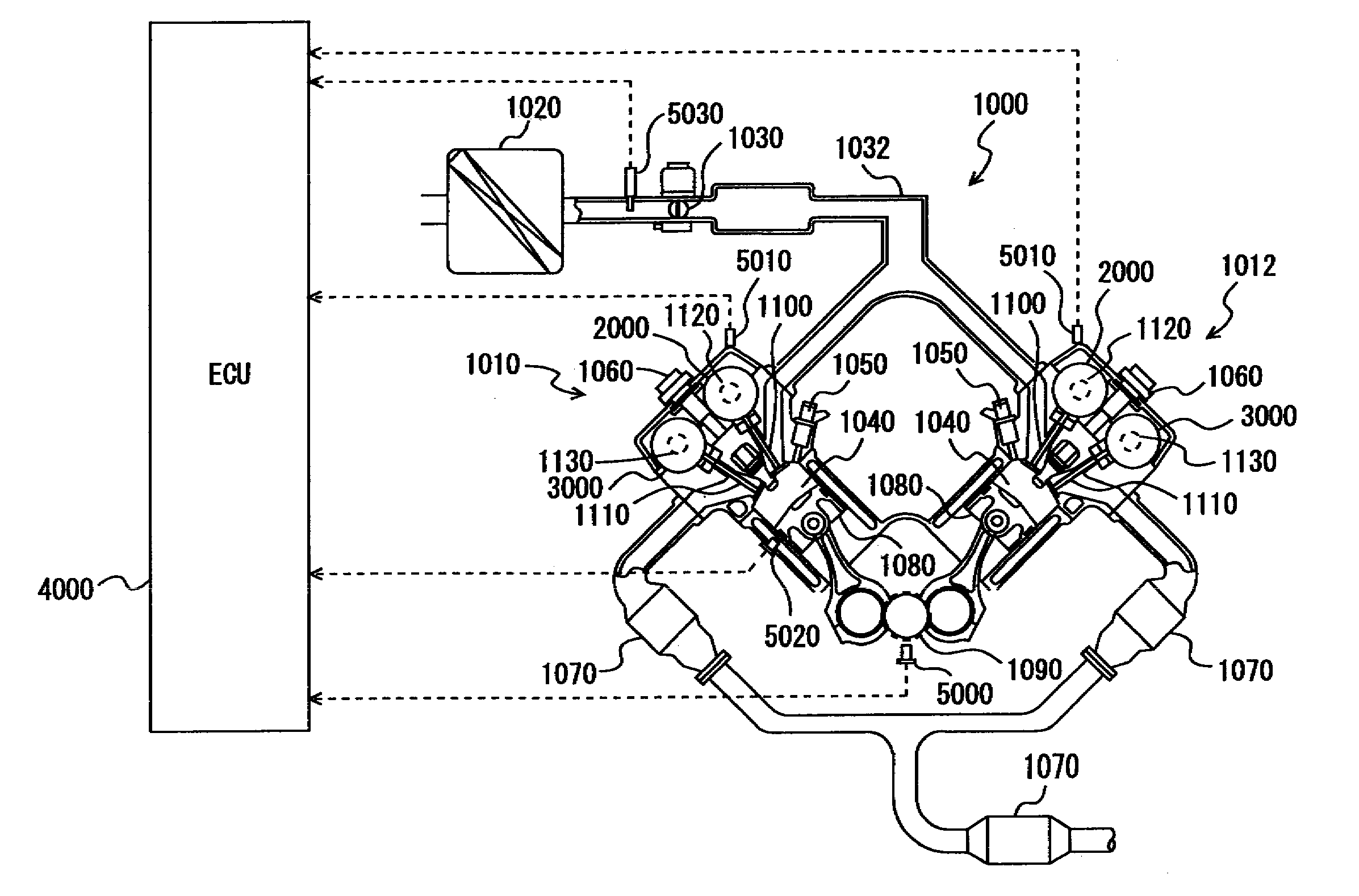
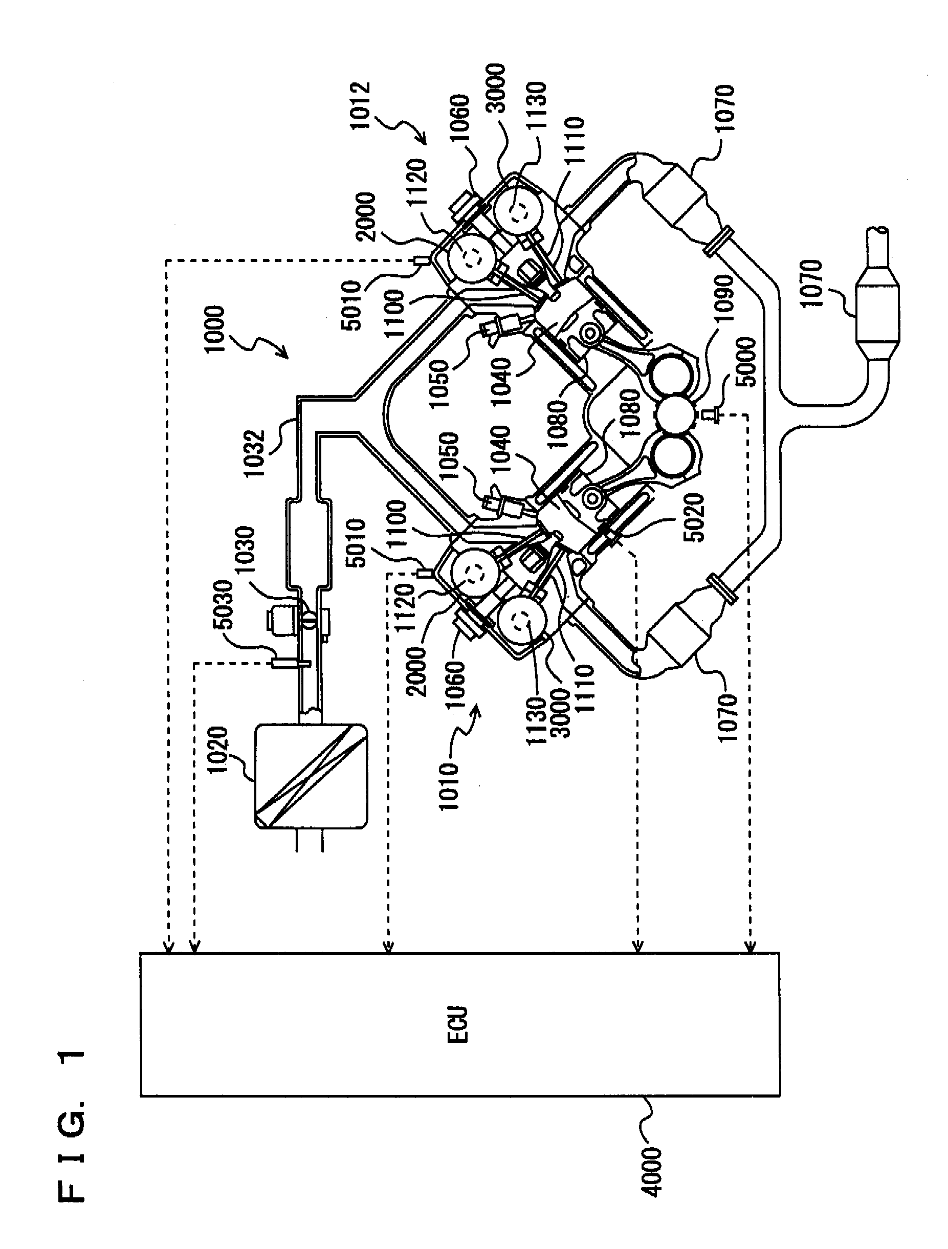
[0032]Referring to FIG. 1, a description is given of an engine of a vehicle on which a variable valve timing apparatus is mounted, according to a first embodiment of the present invention.

[0033]An engine 1000 is a V-type 8-cylinder engine having an “A” bank 1010 and a “B” bank 1012 each including a group of four cylinders. Here, any engine other than the V8 engine may be used.

[0034]Into engine 1000, air is sucked from an air cleaner 1020. The quantity of sucked air is adjusted by a throttle valve 1030. Throttle valve 1030 is an electronic throttle valve driven by a motor.

[0035]The air is supplied through an intake manifold 1032 into a cylinder 1040. The air is mixed with fuel in cylinder 1040 (combustion chamber). Into cylinder 1040, the fuel is directly injected from an injector 1050. In other words, injection holes of injector 1050 are provided within cylinder 1040.

[0036]The fuel is injected in the intake stroke. The fuel injection timing is not limited to the intake stroke. Furth...

second embodiment

[0095]In the following, a second embodiment of the present invention will be described. The present embodiment differs from the foregoing first embodiment in that the target phase of intake valve 1100 is not determined to be in the third region between CA (1) and CA (2). The other structure is the same as that of the foregoing first embodiment. The function is also the same. Therefore, the detailed description thereof will not be repeated here.

[0096]As shown in FIG. 12, in the map for use to determine the phase (target phase) of intake valve 1100, the phase in the first region between the most retarded angle and CA (1) and the phase in the second region between CA (2) and the most advanced angle are defined. On the other hand, the phase in the third region between CA (1) and CA (2) is not defined.

[0097]Thus, it can be restrained that intake VVT mechanism 2000 is controlled such that the phase falls in the third region where the reduction gear ratio varies. Therefore, it can be restr...

third embodiment

[0099]In the following, a third embodiment of the present invention will be described. The present embodiment differs from the foregoing first embodiment in that, in the case where the phase of the intake valve is in the first region from the most retarded angle to CA (1), if engine speed NE is equal to or lower than threshold value NE (0), the power supply to electric motor 2060 is stopped to maintain the phase. The other structure is the same as that of the foregoing first embodiment. The function is also the same. Therefore, the detailed description thereof will not be repeated here.

[0100]Referring to FIG. 13, the control structure of a program executed by ECU 4000 that controls the variable valve timing apparatus in accordance with the present embodiment will be described. It is noted that the same processes as those in the foregoing first embodiment will be denoted with the same step numbers and the description thereof will not be repeated here.

[0101]At S200, ECU 4000 detects e...


PUM


Abstract

An ECU executes a program including the step of stopping power supply to an electric motor if a phase of an intake valve is in a first region between the most retarded angle and CA. In the case where the phase of the intake valve is in the first region, the rotational speed of relative rotation between the output shaft of the electric motor and a sprocket is reduced at reduction gear ratio R thereby to vary the phase of the intake valve. In the case where the phase of the intake valve is in a second region between CA and the most advanced angle, the rotational speed of the relative rotation is reduced at reduction gear ratio R thereby to vary the phase of the intake valve.

Description

TECHNICAL FIELD[0001]The present invention relates to a variable valve timing apparatus and a control method therefor. In particular, the invention relates to a variable valve timing apparatus that varies the timing at which a valve is opened / closed by a variation amount according to an operation amount of an actuator, and a control method therefor.BACKGROUND ART[0002]VVT (Variable Valve Timing) has conventionally been known that changes the phase (crank angle) in (at) which an intake valve or an exhaust valve is opened / closed, according to an operating condition. Generally, the VVT changes the phase by rotating, relative to a sprocket or the like, a camshaft that causes the intake valve or exhaust valve to open / close. The camshaft is rotated by such an actuator as hydraulic or electric motor. Particularly, in the case where the electric motor is used to rotate the camshaft, the torque for rotating the camshaft is difficult to obtain, as compared with the case where the camshaft is ...

Claims


Application Information

Patent Timeline
IPC IPC(8): F02D41/00F01L1/34
CPCF01L1/352F01L1/00
Inventor MASHIKI, ZENICHIROINOUE, YASUMICHIMORIYA, YOSHIHITOURUSHIHATA, HARUYUKI
Owner TOYOTA JIDOSHA KK
Learn More