Distance measuring device and method for determining a distance, and a suitable reflective member

a technology of distance measurement and distance, applied in the direction of using electrical/magnetic means, structural/machine measurement, instruments, etc., can solve the problems of mechanically moving the externally fitted magnetic switch to adjust the switching distance, accompanied by the associated additional material, fitting, adjustment and installation costs, etc., to achieve the effect of versatile possibilities and simple handling

Active Publication Date: 2010-09-09
ASTYX GMBH
View PDF7 Cites 7 Cited by
  • Summary
  • Abstract
  • Description
  • Claims
  • Application Information

AI Technical Summary

Benefits of technology

[0020]Various embodiments of the present invention provide a distance measuring device and a method for determining the distance that enables continuous and therefore discretisable distance determination, simple handling and versatile possibilities for use.

Problems solved by technology

For this the use of non-ferromagnetic materials is predominantly required and so restricts the structural properties and applications of the drive.
For each position to be detected in addition a further sensor must consequently be fitted, accompanied by the associated additional material, fitting, adjustment and installation costs.
Here the cylinder is often already integrated into a machine which is difficult to access, and adjustment of the switching distances by mechanically moving the externally fitted magnetic switches is no longer possible.
Furthermore, for these externally fitted sensors additional installation space is required.
Moreover, with this measuring principle, the possible applications are restricted by interfering static and dynamic magnetic fields (EMV, field of a nearby cylinder) and the temperature characteristics of the sensor.
Both fitting possibilities mean substantially increased complexity, are prone to interference or weaken the stability of the drive in the case of the hollow piston rod.
Ultrasound sensors are only suitable to a limited degree for the path measurement in pneumatic and hydraulic cylinders because the measuring accuracy changes with the cylinder pressure.
Neither the continuous nor the discrete piston position determination can be integrated into a cylinder or can only be so with substantial structural complexity and the associated high costs.
The substantial structural complexity is due to the fact that all of the established sensor principles described must be adapted to the corresponding cylinder length because they have a detection range which is too short.
In practice, the measuring system described in the patent application has the following problems for cylinders with a large diameter (>50 mm): the plastic ring for the piston stop and the antenna retainer is first of all very large.
For larger diameters expensive custom-built models are required.
Moreover, plastic absorbs water over time or releases water according to the conditions of use, and in this way changes the measuring conditions.
The measurement results then become inaccurate and no longer correspond to the specification.
Classic end position damping, e.g. of the pneumatic piston can only be achieved secondly by the moved brake ring made of plastic at the expense of measuring accuracy.
Further disadvantages of the measuring system described in patent application No. 102 05 904.7 are: that the conventional pistons in the pneumatic cylinder are relatively thin and generally have a magnetic ring in the center in order to enable operation with externally fitted Reed switches.
These pistons do not form an ideal reflective member for an electromagnetic wave.
Part of the electromagnetic wave passes over the piston into the functional space of the cylinder lying behind this, returns with a time delay and interferes with the useful signal.
This substantially worsens the measuring accuracy.
Furthermore, a disadvantage of a piston stop in the cover made of plastic is that the plastic is settled by frequent piston impacts and so the physical conditions in the functional space of the cover change for the high frequency sensor.
Moreover, the measuring accuracy worsens.
In addition, with smaller cylinder diameters it is very difficult to integrate the discrete electronics into the cylinder cover.

Method used


Image

  • Distance measuring device and method for determining a distance, and a suitable reflective member
  • Distance measuring device and method for determining a distance, and a suitable reflective member
  • Distance measuring device and method for determining a distance, and a suitable reflective member

Examples


Embodiment Construction

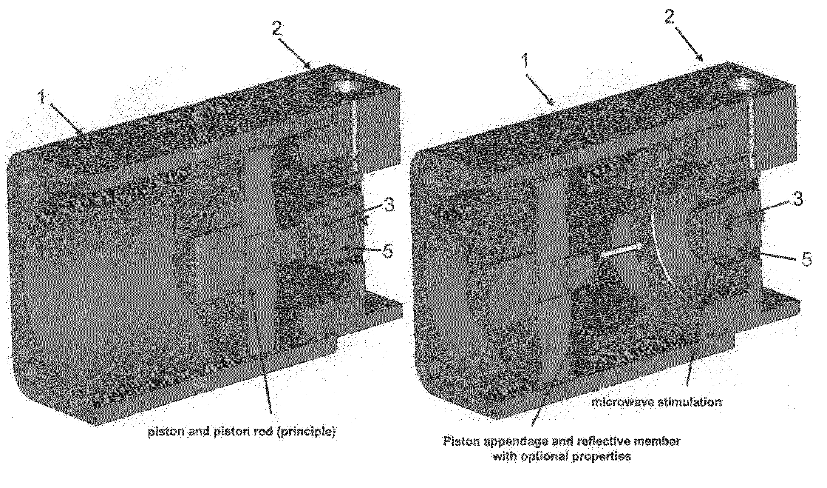
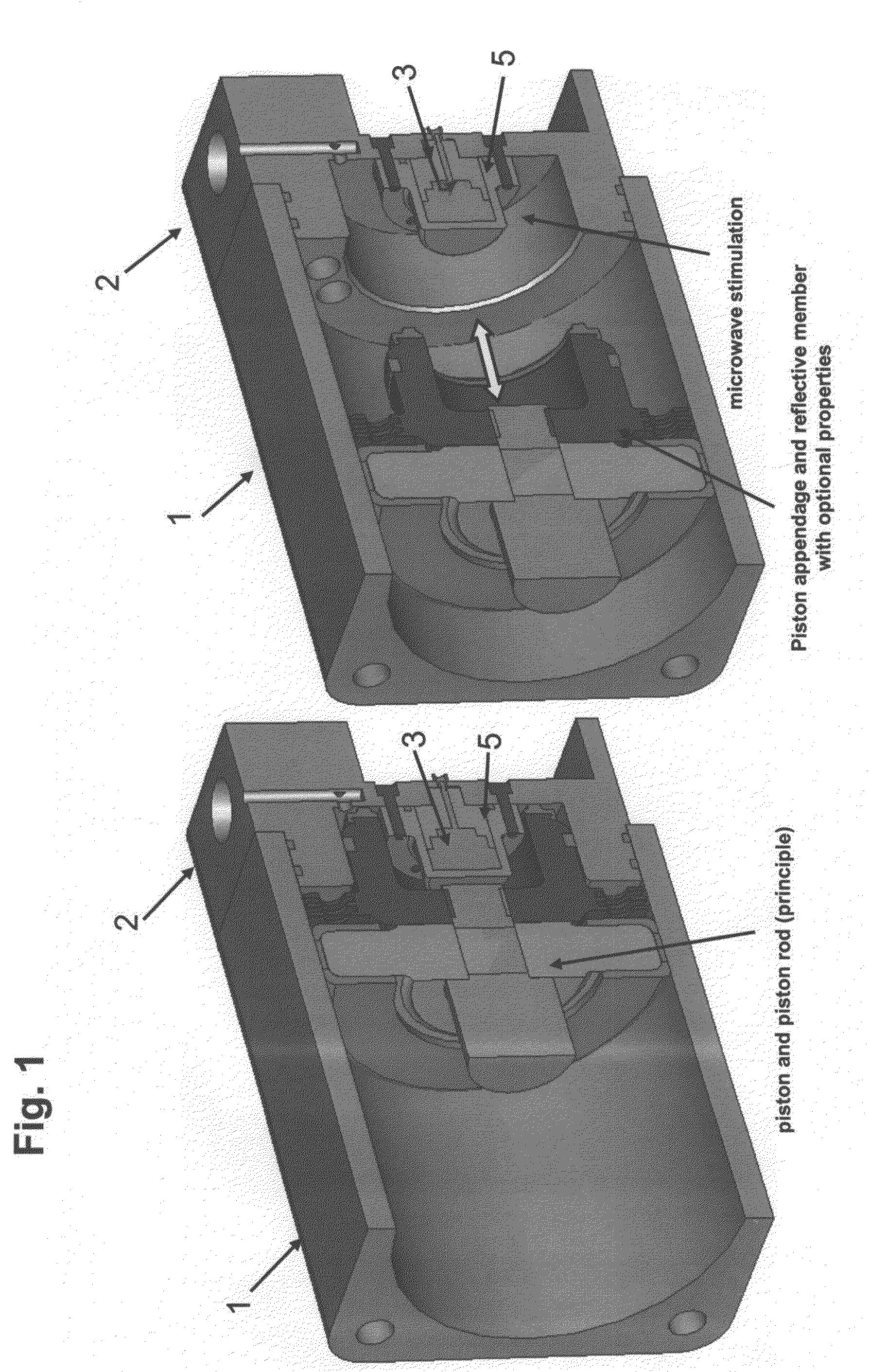
[0041]In FIG. 1 the distance measuring device according to various embodiments is illustrated with a line structure 1 and a feed block with a feed region 2, the feed region having a coupling probe 3 via a dielectric restraint system 5 with the waveguide. In addition, the dielectric secondary ring 9 is illustrated which serves on the one hand as a mechanical stop safeguard and is designed as a secondary adjustment and radiation system.

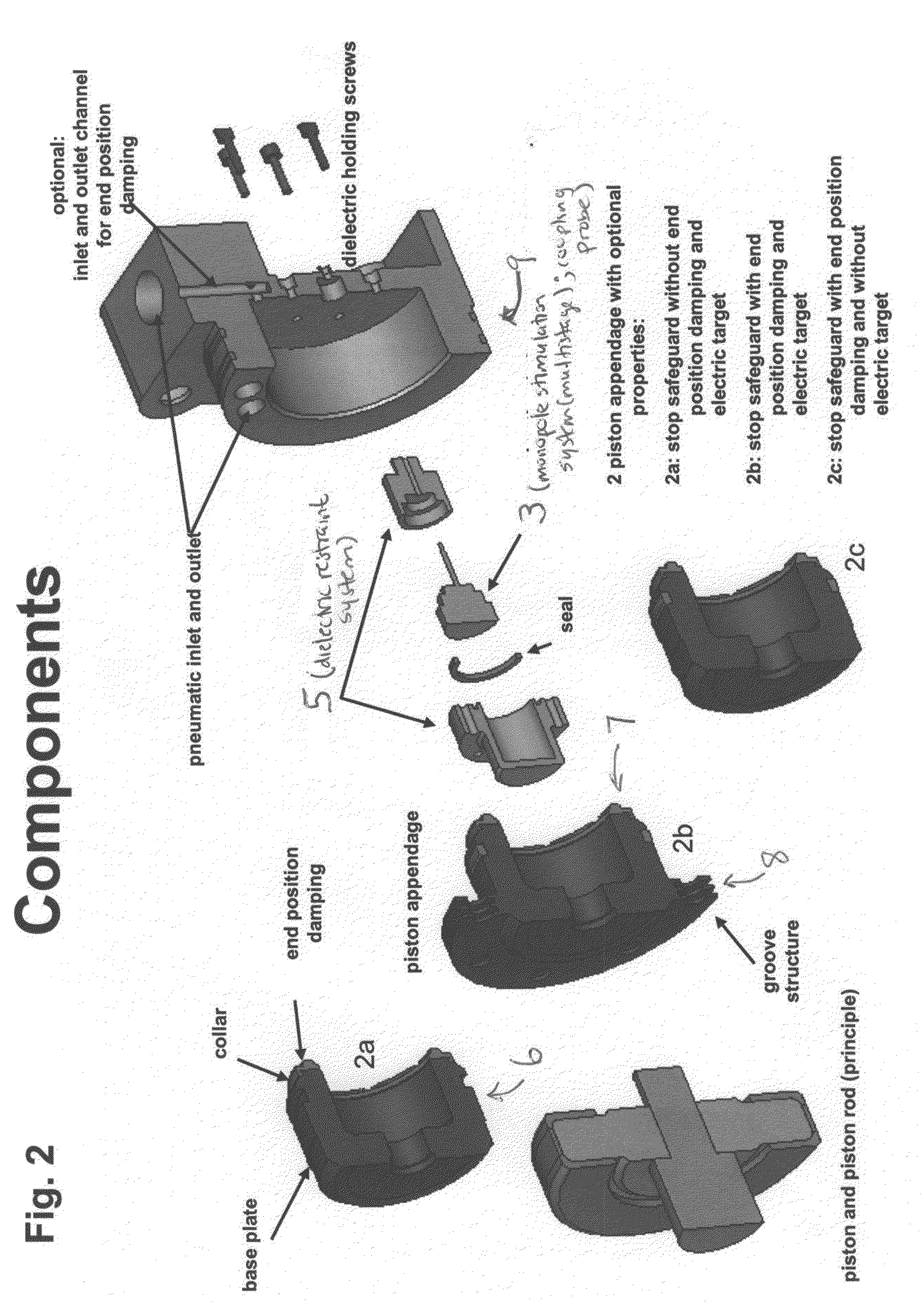
[0042]The respective components of the distance measuring device are illustrated more clearly in FIGS. 2-9, the essential components such as the feed block with a feed region 2 being reproduced in an exploded view in FIG. 2. It can also clearly be seen that the dielectric restraint system 5 holds the coupling probe 3 in the form of a monopole stimulation system which includes a pin which can be accommodated in a coaxial waveguide. In addition the dielectric secondary ring 9 is shown. Likewise, the reflective member with the attached collar for forming a...


PUM

PropertyMeasurementUnit
frequencyaaaaaaaaaa
frequencyaaaaaaaaaa
pressureaaaaaaaaaa

Abstract

A distance measuring device and a method for determining a distance are provided. The distance measuring device includes a reflective member, evaluation electronics and a sensor device having at least one coupling probe for feeding a transmission signal into a line structure with the reflective member. The reflective member includes a base plate with an attached collar for forming a cup-shaped element.

Description

CROSS REFERENCE TO RELATED APPLICATIONS[0001]This application claims priority to and the benefit of the filing date of PCT Application No. PCT / EP2007 / 007259, filed Aug. 16, 2007 and German Patent Application No. DE 10 2006 038 469.5, filed Aug. 17, 2006, both of which are each hereby incorporated by reference in their entirety.BACKGROUND OF THE INVENTION[0002]The present invention relates to a distance measuring device as well as to a method for determining a distance and to a suitable reflective member.[0003]Conventional distance measuring devices are used among other things for example for detecting the piston position of fluidic linear drives and pneumatic and hydraulic cylinders. The detection of the piston position on cylinders can be implemented both discretely, i.e. at discrete points, and continuously, i.e. constantly during operation.[0004]A discrete piston position determination is generally required in order to report back the implementation or end of a piston movement to...

Claims


Application Information

Patent Timeline
Patent Type & Authority Applications(United States)
IPC IPC(8): G01M15/06
CPCF15B15/222F15B15/2869Y10T29/49826G01B15/00G01B7/14
Inventor TRUMMER, GUENTHER
Owner ASTYX GMBH
Why Eureka
Try Eureka