Blade control system

a control system and blade technology, applied in the direction of machines/engines, mechanical equipment, transportation and packaging, etc., can solve the problems of yaw error, different forces acting on the rotor, and slow rotational speed of the rotor, so as to reduce the risk of a blade striking and minimize costs and maintenance

Inactive Publication Date: 2010-09-09
DEERING KENNETH JAMES
View PDF6 Cites 39 Cited by
  • Summary
  • Abstract
  • Description
  • Claims
  • Application Information

AI Technical Summary

Benefits of technology

[0014]The representative embodiments and modes of operation of the components and system described herein provide a plurality of blade control and positioning functions which may be employed individually, or in a combined fashion, and thereby provide a means of overcoming the various noted shortcomings of the prior art in blade control systems. In this manner, the device and method herein provided an improved system for blade control for such wind turbines while concurrently reducing the risk of a blade of a flapping hinge rotor from striking the tower whilst minimizing the need (and costs) for substantial additions of blade stiffness.
[0015]In one mode of blade control herein described and disclosed, the representative embodiments may include a rotor azimuth sensor. The rotor azimuth sensor can, in its most simple form, be a two position switch such as a non-contact proximity sensor. Each proximity sensor is used to register the critical zone in the rotation azimuth of each blade when there is a danger of interfering with the tower. For example, a different proximity sensor may be associated with each blade and each proximity sensor is used to register the critical zone in the rotational azimuth of its associated blade. Alternatively, the rotor azimuth sensor can employ multiple detection devices for each blade and thereby provide additional information to the control system. When a blade is within the critical azimuth zone, the flap angle target for that particular blade is adjusted to a larger value. As a consequence of the increased flap angle target, the bending loads on the blade are substantially diminished and the blade is no longer deflected toward the tower. Once the blade has past the critical azimuth zone, its flap angle target is returned to the normal value for shut-down. This technique can be applied individually to all blades.
[0025]In the pitch control component of the disclosed system and method herein, the representative components described herein provide a means to mitigate or attenuate aerodynamic loading induced flap angle excursions by adding a flap position signal for each blade, to the input data to a control computer input. In this segment of the system herein, a control computer continuously monitors the flap angle signals from each blade. In the event of a blade experiencing a significantly differing aerodynamic load condition and consequent flap excursion, this will be immediately recognized by the control computer. The control computer software can be coded to respond to either a flap position excursion or a flap rate excursion or combinations of both. In the presence of a flap excursion, the control computer will adjust the pitch position or pitch rate command to the individual blade undergoing the excursion. The affect of the pitch adjustment will be to alter the aerodynamic loading acting on the blade and thereby attenuate or mitigate the flap excursion and avoid potentially damaging structural loads.
[0038]i) inhibits rotational resistance of said rotor to permit movement of said rotor between different yaw positions relative to a vertical axis of said turbine;
[0045]It is another object of this invention to provide such a control system which may be employed with a flapping hinged rotor to reduce the risk of a blade striking the support tower.
[0046]It is a further object of this invention, to provide such a modular control system which also minimizes costs and maintenance.

Problems solved by technology

As the direction of wind changes over time, the rotor's rotational axis may no longer be optimally aligned to (e.g. substantially in parallel to) the direction of the wind, which gives rise to yaw error.
The blades, therefore, capture less energy from the wind, and may cause the rotational speed of the rotor to slow down.
Yaw error gives rise to different forces acting on the rotor.
A rotor with yaw error can therefore expose its blades to greater fatigue loads.
If such loads are not properly controlled or averted, damage may arise to the rotor or structure of the wind turbine.
However, in the absence of power to the motor, the gears hold the rotor in a fixed yaw position.
This approach involves the use of multiple parts which leads to multiple points of potential failure or mechanical wear.
However, the yaw position of such wind turbines will depend entirely on the direction of the wind, and cannot be otherwise controlled or selectively adjusted.
A further problem with the above approaches to yaw control is that when no power is supplied to a wind turbine's control systems or mechanisms (e.g. when the wind turbine has shut down), wind may still blow against the blades of the wind turbine.
The worm gear approach, as well as the spring applied brake approach, will hold the yaw position of the rotor in the absence of power and thus, will not maintain a favorable orientation with the incident wind.
Such rotors will experience greater mechanical stress as the control structures of wind turbine will be configured to resist such rotation or adjustment in the absence of power which may increase the maintenance problems and requirements of the wind turbine.
However, variations in wind speed can present problems for the rotor.
Structural damage may result if there is insufficient centrifugal force to bias the blades in the outward configuration (e.g. the blades may collapse together).
An increased wind speed increases the rotational speed of the rotor, but this can place additional stress on (and potentially damage) the internal control or support structures of the turbine.
In particular, when the blades of a flapping hinge rotor are pitched to produce negative lift (e.g. to slow down the rotor), excessive negative lift can be produced which may cause a part of the blade to strike the tower supporting the rotor.
However, to increase bending stiffness, the blade design must as a consequence either (I) use more materials, (ii) be of larger sectional dimensions, or (iii) employ more expensive materials, all of which increase the cost of the blade.
However, the above solutions to pitch and yaw control are not suitable for flapping hinge rotors.
However, the one blade may experience a substantially different aerodynamic loading and respond with a flap angle excursion.
Sometimes the flap angle excursion can be severe enough to exceed normal operating bounds and induce potentially damaging structural loads (e.g. causing the blade to strike the tower).
Another problem related to the employment of flapping hinge rotors is that when the blades of the rotor are pitched to produce negative lift (to slow down the rotor), excessive negative lift can be produced which may cause a part of the blade to strike the tower supporting the rotor.

Method used


Image

  • Blade control system
  • Blade control system
  • Blade control system

Examples


Embodiment Construction

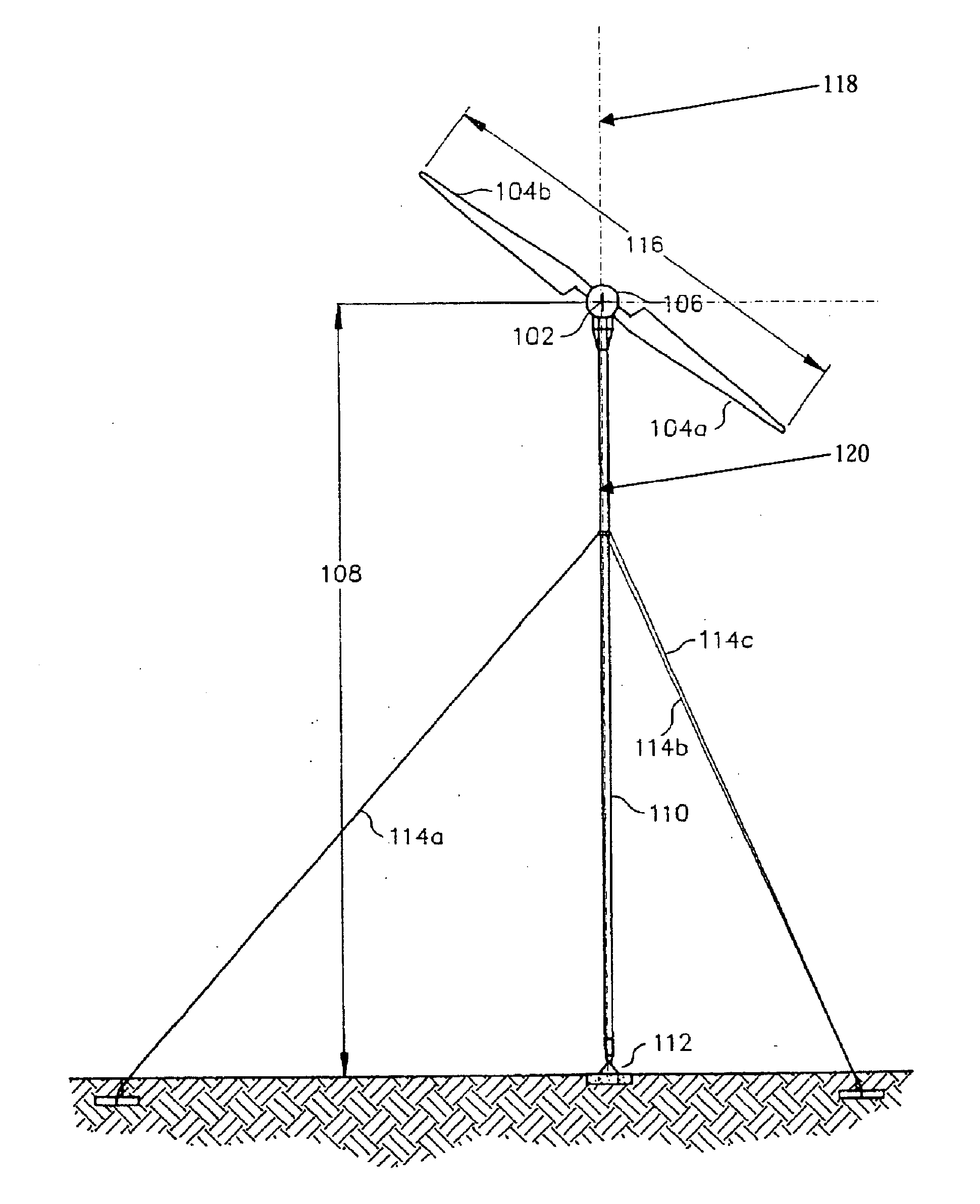
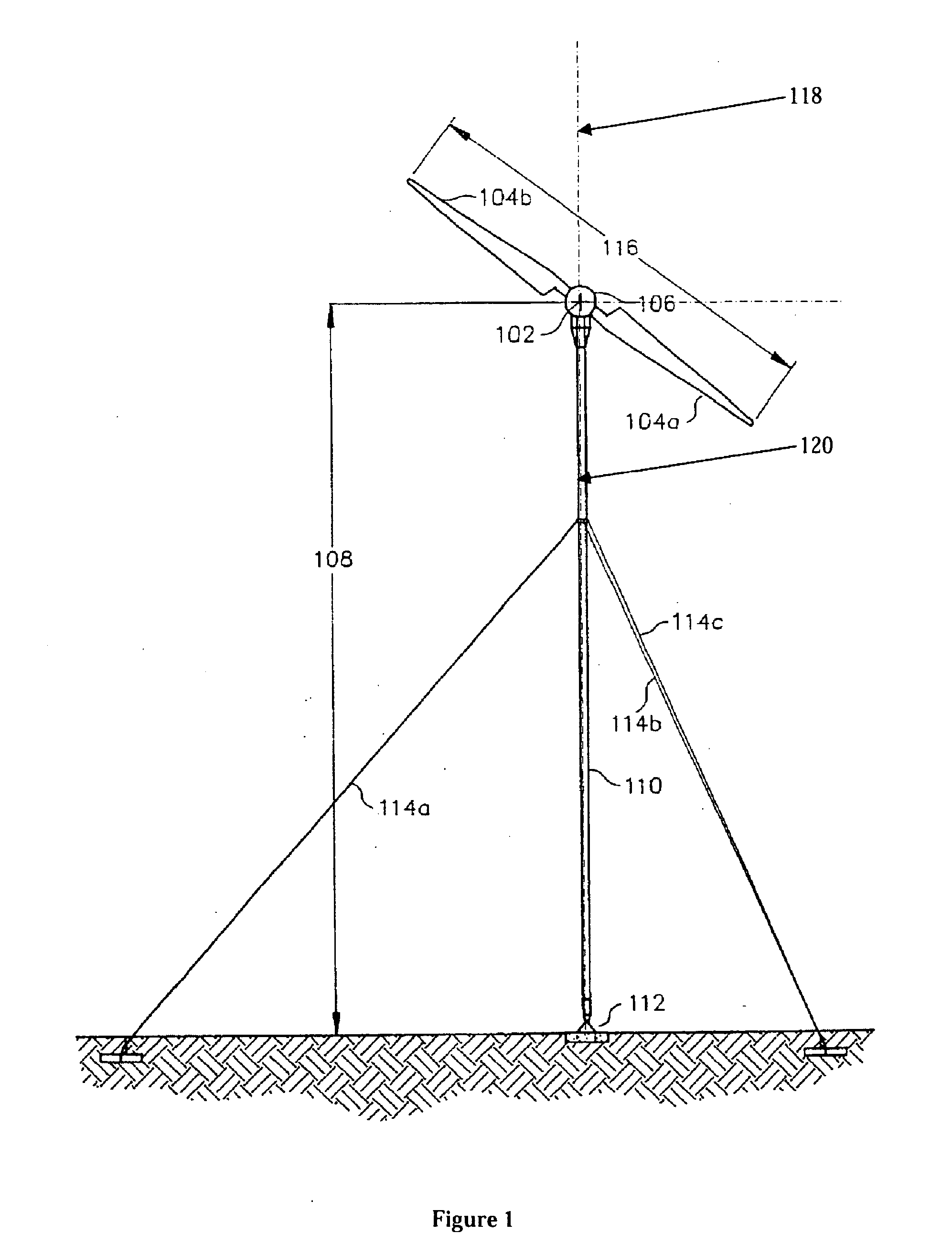
[0061]Referring now to the drawings 1-15, wherein similar parts of the invention are identified by like reference numerals, there is shown in FIG. 1, a wind turbine 100, which includes a plurality of blades 104a and 104b coupled to a hub 302 (see FIG. 3) located within a housing 106. The blades 104a and 104b are rotatable (e.g. together with the hub 302) about a rotational axis 102. A tower 110 supports the housing 106 at a height 108 about the ground. The height 108 should be greater than half the span length 116 of the blades 104a and 104b to avoid the blades from hitting the ground. The tower 110 has a base portion 112 that is connected to the ground. The tower 110 may have one or more guy wires 114a, 114b and 114c connecting the tower 110 to anchors on the ground to help secure and stabilize the tower 110 (e.g. when the wind turbine 100 is operating in high wind conditions).

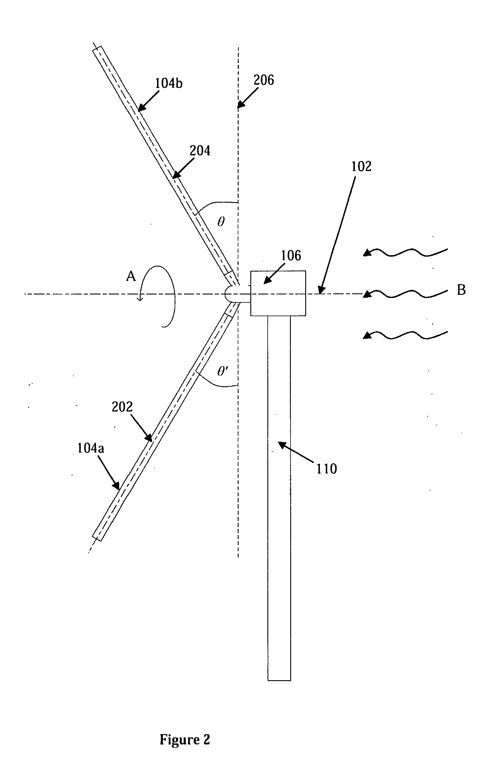
[0062]FIG. 2 is a side view of the wind turbine 100 shown in FIG. 1. The blades 104a and 104b of the wind ...


PUM


Abstract

A wind turbine system for blade control which employs means for adjusting the pitch and yaw of the blades rotating about an axis and the resulting speed of the blades powering a wind turbine. The control system selectively resists movement of said blades to a different incline position based on a comparison of the measured rotational speed with a target speed value, the target speed value being determined based on an energy output level for said turbine. The control system includes at least one adjustable hydraulic actuator for movement of said blades to a different incline position.

Description

FIELD OF THE INVENTION[0001]This application claims priority to Australian Provisional Patent Number 2009 900828 filed Feb. 25, 2009, and Australian Provisional Patent Number 2009 900827 filed Feb. 25, 2009, and Australian Provisional Patent Number 2009 900831 filed Feb. 25, 2009, and Australian Provisional Patent Number 2009 900830 filed Feb. 25, 2009, and Australian Provisional Patent Number 2009 900832 filed Feb. 25, 2009, each of which is respectively incorporated herein in its entirety by reference.[0002]The present invention relates to systems and methods for turbine blade control. More particularly it relates to such a system for blade control which employs means for adjusting the pitch and yaw of the blades rotating about an axis and the resulting speed of the blades powering a wind turbine.BACKGROUND OF THE INVENTION[0003]A typical wind turbine includes a rotor with multiple blades. When the blades are exposed to a sufficient level of airflow, aerodynamic forces created by ...

Claims


Application Information

Patent Timeline
Patent Type & Authority Applications(United States)
IPC IPC(8): F03D7/02
CPCF03D7/0204F03D7/0224F03D7/0236F03D7/024F03D7/0276Y02E10/723F05B2260/76F05B2270/327F05B2270/328F05B2270/604F03D7/042Y02E10/72
Inventor DEERING, KENNETH JAMES
Owner DEERING KENNETH JAMES
Why Eureka
Try Eureka