
Method for the prevention of nanoparticle agglomeration at high temperatures

a nanoparticle agglomeration and high temperature technology, applied in the field of nanoparticles, can solve the problems of reducing particle specific surface area, reducing the effectiveness of various applications, and lack of consistent distribution and density

Inactive Publication Date: 2010-09-09
APPL NANOSTRUCTURED SOLUTIONS LLC
View PDF110 Cites 36 Cited by
  • Summary
  • Abstract
  • Description
  • Claims
  • Application Information

AI Technical Summary

Problems solved by technology

The sintering and agglomeration of the nanoparticles result in reduced particle specific surface areas and consequently diminished effectiveness in various applications.
Such discrete particles can also be mobile on a surface leading to a lack of consistent distribution and density.
Moreover, the channels can be of substantial depth and dimensions such that they impact the subsequent reaction chemistry of the nanoparticle.

Method used

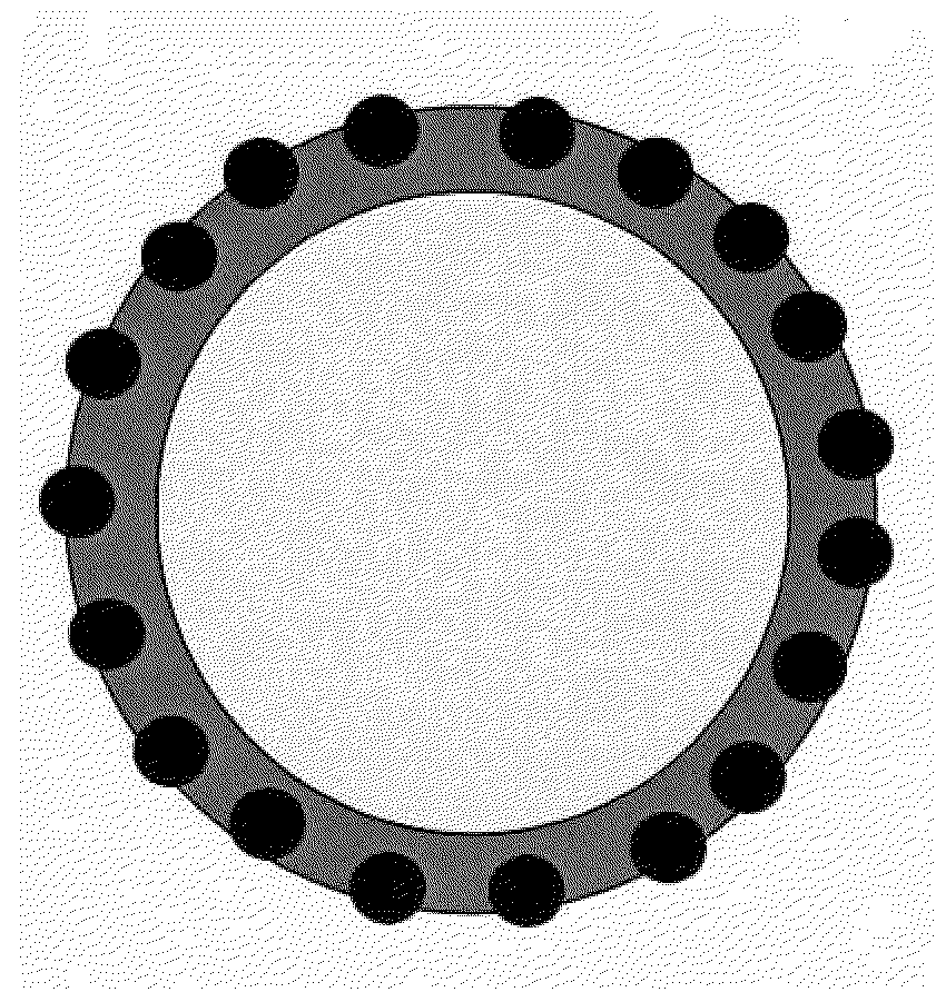
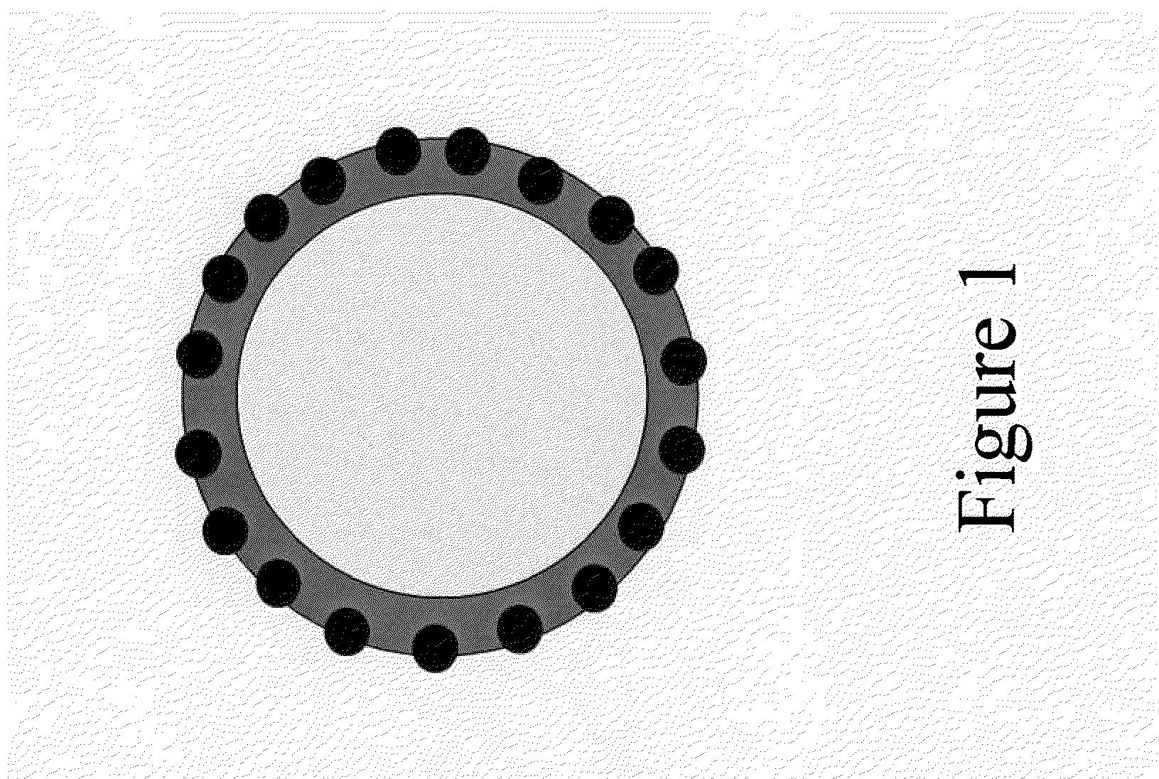
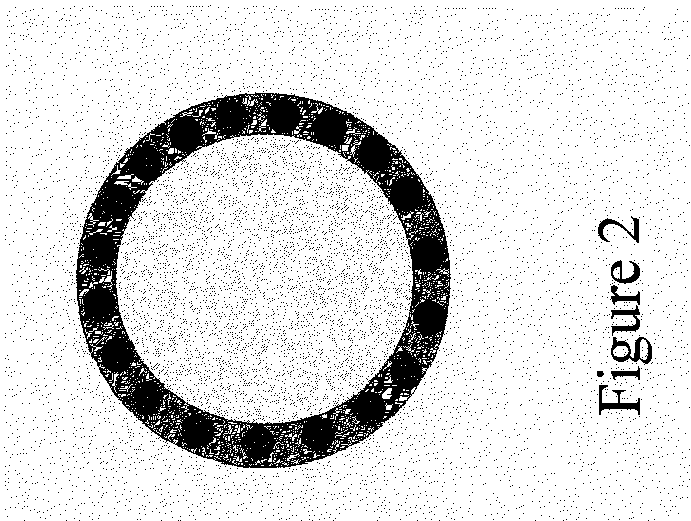

Image

  • Method for the prevention of nanoparticle agglomeration at high temperatures
  • Method for the prevention of nanoparticle agglomeration at high temperatures
  • Method for the prevention of nanoparticle agglomeration at high temperatures

Examples


example i

[0067]This example shows how a barrier layer can be used in a ceramic fiber composite structure to prevent sintering of iron nanoparticles applied to the ceramic fiber surface for enhanced signature control characteristics.

[0068]FIG. 4 depicts system 400 for producing a high temperature ceramic fiber composite with enhanced signature control characteristics in accordance with the illustrative embodiment of the present invention. System 400 includes a ceramic fiber 402, barrier coating solution bath 404, nanoparticle solution bath 406, coating curing system 408, filament winding system 410, and a resin infusion system 412, interrelated as shown.

[0069]The ceramic fiber 402 used is a Silicon Carbide Sylramic™ fiber tow (1600 denier10 micron diameter) (COI Ceramics, Inc).

[0070]A barrier coating 404, consisting of the Starfire SMP-10, RD-212a solution is applied to the ceramic fiber 402 via a dip process. A diluted solution of 1 part SMP-10 and 10 parts isopropyl alcohol is used in the d...

example ii

[0076]This example shows how carbon nanotubes (CNTs) can be grown on the surface of a carbon fiber using a barrier coating to prevent sintering of the iron nanoparticle catalyst.

[0077]FIG. 5 depicts system 500 for producing CNTs on carbon fiber (34-700 12 k unsized carbon fiber tow with a tex value of 800—Grafil Inc., Sacramento, Calif.) in accordance with the illustrative embodiment of the present invention. System 500 includes a carbon fiber material payout and tensioner station 505, plasma treatment station 515, barrier coating application station 520, air dry station 525, catalyst application station 530, solvent flash-off station 535, CNT-growth station 540, and carbon fiber material uptake bobbin 550, interrelated as shown.

[0078]Payout and tension station 505 includes payout bobbin 506 and tensioner 507. The payout bobbin delivers an unsized carbon fiber material 560 to the process; the fiber is tensioned via tensioner 507. For this example, the carbon fiber is processed at a ...


PUM

PropertyMeasurementUnit
sizeaaaaaaaaaa
temperatureaaaaaaaaaa
spherical diameteraaaaaaaaaa

Abstract

A method includes: (a) conformally depositing a barrier coating, provided in liquid form, on at least one surface of a substrate; (b) embedding a plurality of nanoparticles in the barrier coating to a selected depth; and (c) fully curing the barrier coating after embedding the plurality of nanoparticles; the embedded plurality of nanoparticles are in continuous contact with the cured barrier coating. The order in which the barrier coating and nanoparticles are deposited on the substrate can be switched or they can be deposited simultaneously. An article includes a substrate having a cured barrier coating conformally disposed on at least one surface of the substrate and a plurality of nanoparticles embedded to a selected depth in the barrier coating creating an embedded portion of each of the plurality of nanoparticles. The embedded portion of each of the plurality of nanoparticles in continuous contact with the cured barrier coating.

Description

STATEMENT OF RELATED APPLICATIONS[0001]The present invention claims priority under 35 U.S.C. §119(e) to provisional applications 61 / 157,096 filed Mar. 3, 2009, and 61 / 182,153 filed May 29, 2009 each of which is incorporated by reference herein in their entirety.STATEMENT REGARDING FEDERALLY SPONSORED RESEARCH OR DEVELOPMENT[0002]Not applicable.FIELD OF THE INVENTION[0003]The present invention relates to nanoparticles, more specifically to nanoparticles used in high temperature processes.BACKGROUND OF THE INVENTION[0004]Many nanoparticles are used in applications that involve gas phase reactions which can expose the nanoparticles to elevated temperatures. It has been observed that with decreasing particle size, the melting point of the nanoparticle also decreases. The reduced melting point coupled with surface diffusion characteristics (driven by the large surface area to volume ratio) of nanoparticles on various substrates can cause sintering and particle agglomeration during high t...

Claims


Application Information

Patent Timeline
Patent Type & Authority Applications(United States)
IPC IPC(8): B32B5/16B05D3/10H05H1/00B05D1/36B32B7/02
CPCB01J21/185Y10T428/2495B01J35/0013B01J37/0219B82Y30/00B82Y40/00C01B31/0233D06B1/02D06B3/10D06B19/00D06M11/74C01B31/0226Y10S977/842Y10T428/25B01J23/745C01B32/162C01B32/16B01J35/23
Inventor SHAH, TUSHAR K.MALET, BRANDON K.LEDFORD, JORDAN T.MALECKI, HARRY C.
Owner APPL NANOSTRUCTURED SOLUTIONS LLC
Learn More