Dual Fuel Compression Ignition Engines and Methods

a compression ignition and dual fuel technology, applied in the direction of machines/engines, mechanical equipment, non-mechanical valves, etc., can solve the problems of inability to control the time of ignition, natural gas has the disadvantage of not being liquifyable at ordinary temperatures, and the use of fuel that must be maintained at cryogenic temperatures in ordinary vehicles, such as passenger cars and trucks, is not practical

Active Publication Date: 2010-09-16
STURMAN DIGITAL SYST
View PDF13 Cites 36 Cited by
  • Summary
  • Abstract
  • Description
  • Claims
  • Application Information

AI Technical Summary

Problems solved by technology

However the use of injected diesel fuel for compression ignition worked satisfactorily, in that the self ignition temperature of the gaseous fuel typically is too high to self ignite in a conventional diesel engine, and further, if self ignition could be obtained, there would be no way to control the time of ignition, unless the gaseous fuel was injected into the combustion chamber at the appropriate time, rather than being mixed with the intake air.
However natural gas has the disadvantage of not being liquifyable at ordinary temperatures, though does turn to a liquid at cryogenic temperatures.
The use of a fuel that must be maintained at cryogenic temperatures in ordinary vehicles, such as passenger cars and trucks, is not practical.
Accordingly for such use, natural gas must be stored in pressurized form, highly limiting the energy per unit of volume (energy density) of the compressed natural gas.
Thus when used to power a vehicle, alone with spark ignition or in conjunction with sufficient diesel fuel for compression ignition in motor vehicles, the range of the vehicle is highly limited.
Ignition temperatures are limited by a very limited air content in the combustion chamber, with additional air being injected after ignition to continue combustion to completely consume the fuel, and provide enough excess air (with or without some additional air intake) in the residual exhaust gas for the following combustion ignition while still limiting combustion chamber temperatures to below the temperature at which NOx is formed.

Method used


Image

  • Dual Fuel Compression Ignition Engines and Methods
  • Dual Fuel Compression Ignition Engines and Methods
  • Dual Fuel Compression Ignition Engines and Methods

Examples


Embodiment Construction

[0014]The present invention is intended for use in camless engines wherein an electronic control system has control of engine valve timing and fuel injection. Such engine valve control systems may use hydraulic valve actuation, such as is disclosed in U.S. Pat. No. 6,739,293, though other engine valve control systems may be used. Camless engines wherein an electronic control system has control of engine valve timing and fuel injection include free piston engines, which have neither a camshaft nor a crankshaft coupled to the free pistons.

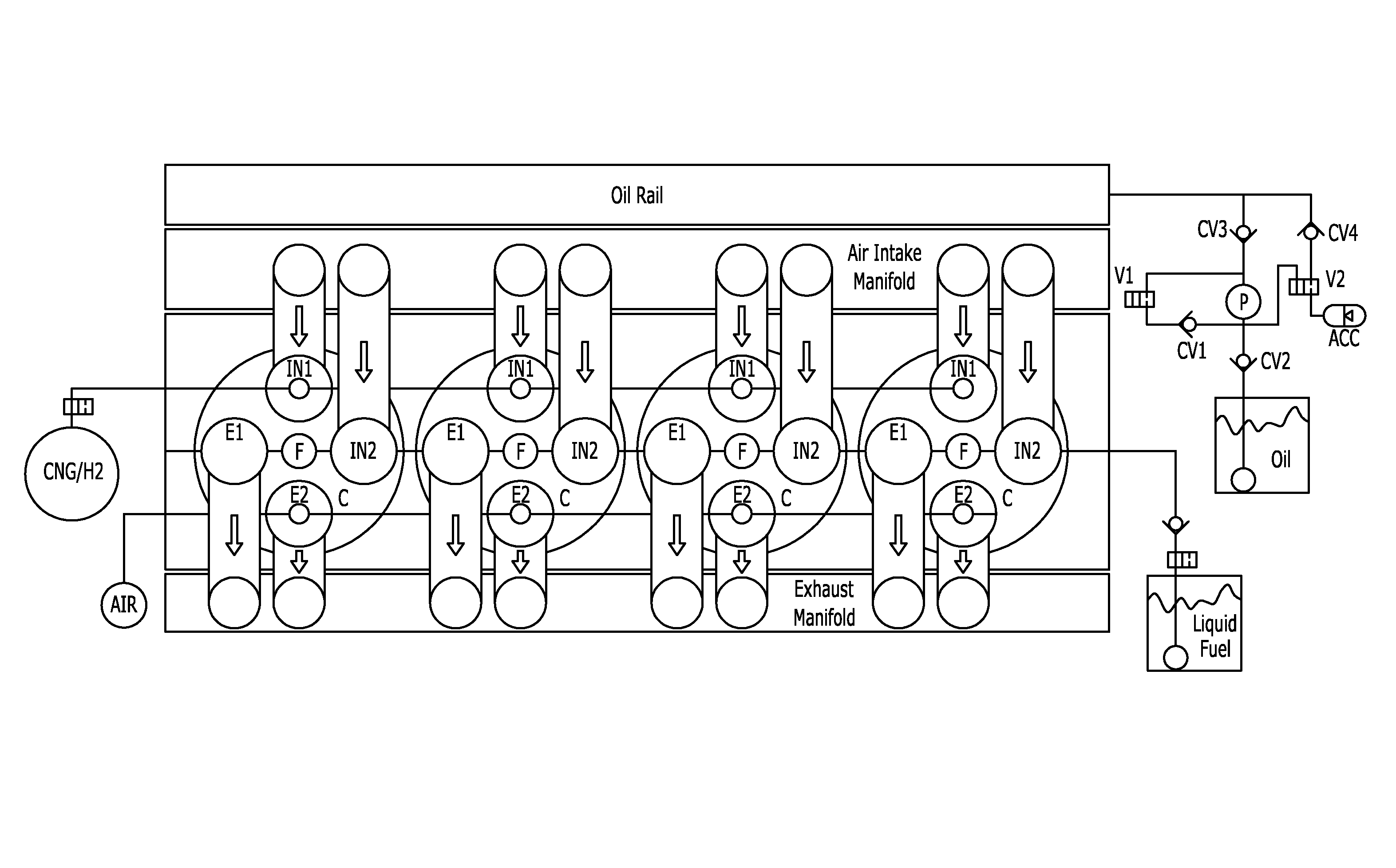
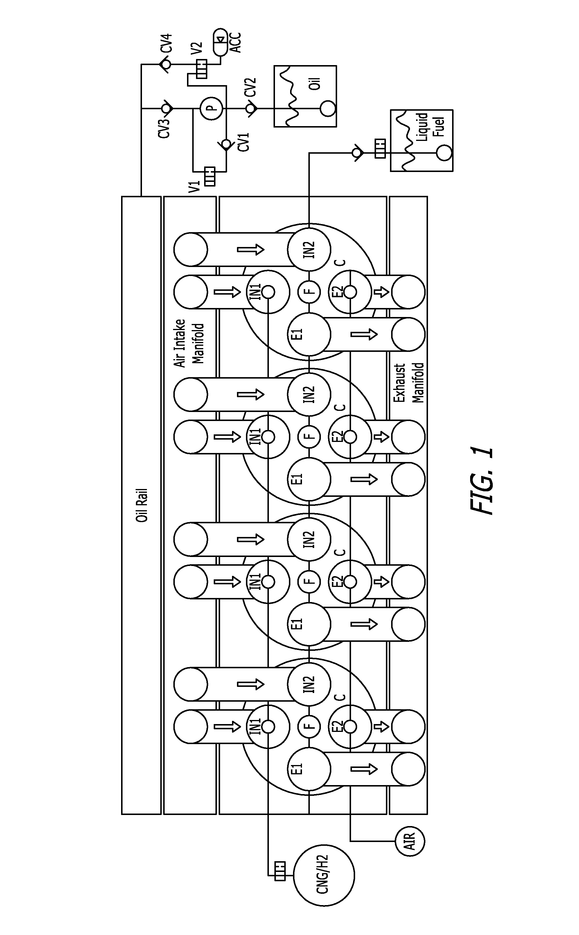
[0015]FIG. 1 is a diagram illustrating a typical four cylinder engine, or alternatively, one bank of a V8 diesel engine. In the engine illustrated, all cylinders have the same configuration, though this is not a limitation of the invention. In particular, in the embodiment of FIG. 1, each cylinder C has two intake valves IN1 and IN2 and two exhaust valves E1 and E2. In addition, each cylinder has a fuel injector F which may of conventional design for...


PUM


Abstract

Dual fuel compression ignition engines and methods that allow compression ignition on gaseous fuels like compressed natural gas, hydrogen and ammonia, yet will run on liquid fuels, including diesel fuels for such purposes as starting or when the gaseous fuel is not available or has been consumed and greater range or operating time is needed. Ignition of fuels having a high self ignition temperature is assured by recirculating high temperature exhaust gas back into the intake charge before compression. Existing engines may be converted to run as a dual fuel engine by replacement of the engine head or heads. Various embodiments are disclosed.

Description

CROSS-REFERENCE TO RELATED APPLICATION[0001]This application claims the benefit of U.S. Provisional Patent Application No. 61 / 159,031 filed Mar. 10, 2009.BACKGROUND OF THE INVENTION[0002]1. Field of the Invention[0003]The present invention relates to the field of compression ignition engines.[0004]2. Prior Art[0005]Dual fuel compression ignition engines are well known in the prior art. Most commonly, such engines operate on a dual fuel consisting of diesel fuel and natural gas. The combination of a liquid fuel and a gaseous fuel had an advantage in the prior art in that diesel fuel could be injected in controlled amounts through a conventional diesel injector, and the gaseous fuel could be injected into the intake airstream. Typically such engines depend on the use of some diesel fuel to initiate compression ignition, with the gaseous fuel then supplementing the diesel fuel for increased power. Such engines frequently run on 100% diesel fuel at idle, with increasing amounts of gaseo...

Claims


Application Information

Patent Timeline
Patent Type & Authority Applications(United States)
IPC IPC(8): F23C1/08
CPCF01L1/28F02D19/081F02B21/00F02D17/026F02D39/10F02M21/0269F02M21/0275F02M2023/008Y02T10/36Y02T10/32F02D19/061F02D19/0644F02D19/066F02D19/0689F02D19/0692F01L9/02F01L9/10Y02T10/30
Inventor STURMAN, ODED EDDIE
Owner STURMAN DIGITAL SYST
Why Eureka
Try Eureka