Ion conductor

Inactive Publication Date: 2010-09-16
NISSAN MOTOR CO LTD +1
View PDF6 Cites 4 Cited by
  • Summary
  • Abstract
  • Description
  • Claims
  • Application Information

AI Technical Summary

Benefits of technology

[0004]The present invention has been made in order to solve the problem concerning the conventional electrolyte membrane combined with the ceramic film and the ionic liquid. It is an object of the present invention to provide an ion conductor, of which the ion conductivity is

Problems solved by technology

However, the conventional electrolyte membrane combined with such a ceramic film and an ionic liquid has had a proble

Method used


Image

  • Ion conductor
  • Ion conductor
  • Ion conductor

Examples


Example

Example 1

1. Fabrication of Inorganic Porous Film

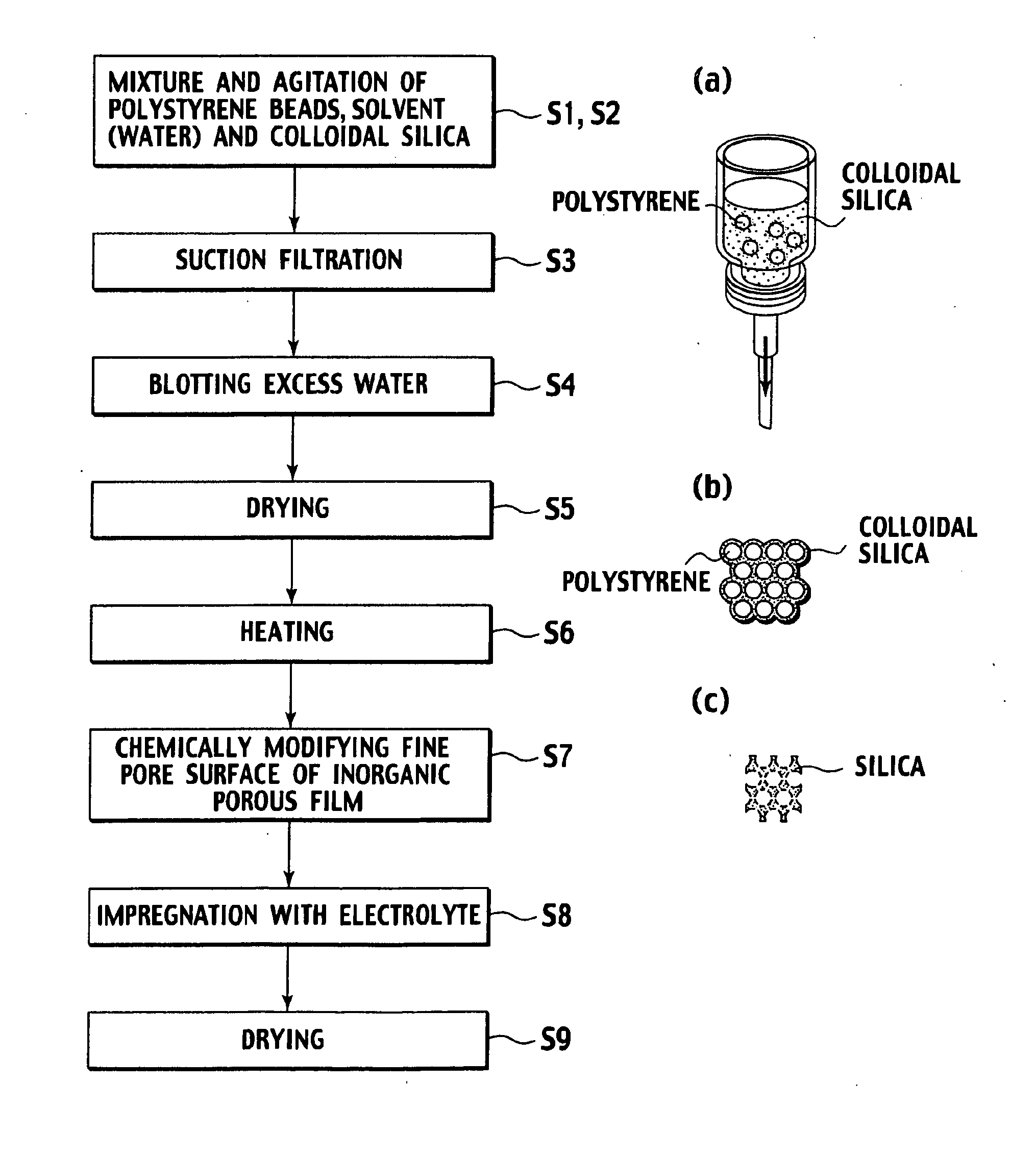
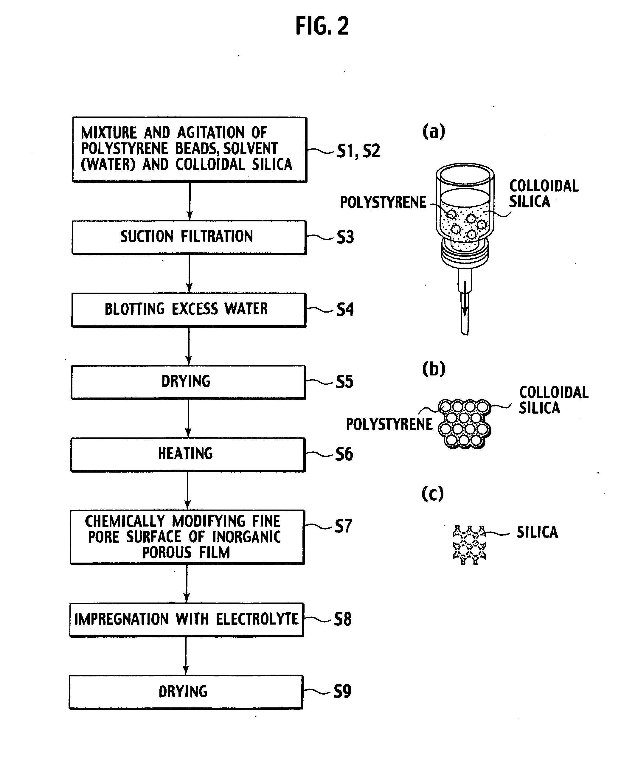
[0061]As a raw material for the inorganic porous film, colloidal silica with a diameter of 70 to 100 nm was prepared. Also, in order to control the fine pore diameter of the inorganic porous film, polystyrene spherical particles with a mean diameter of approximately 500 nm were prepared.

[0062]The colloidal silica and the polystyrene spherical particles were mixed and prepared so that the porous film could have a predetermined film thickness when being formed with regard to a volume of a solute contained in the suspension. As for the procedure, first, the polystyrene spherical particles were weighed so as to be 10%, and added to water to make a solution. Thereafter, the colloidal silica was weighed so as to be 40%, and added to the solution. Then, ultrasonic agitation was performed for the liquid thus obtained, and the suspension in which the particles were uniformly dispersed was obtained.

[0063]Subsequently, a membrane filter was set o...

Example

Example 2

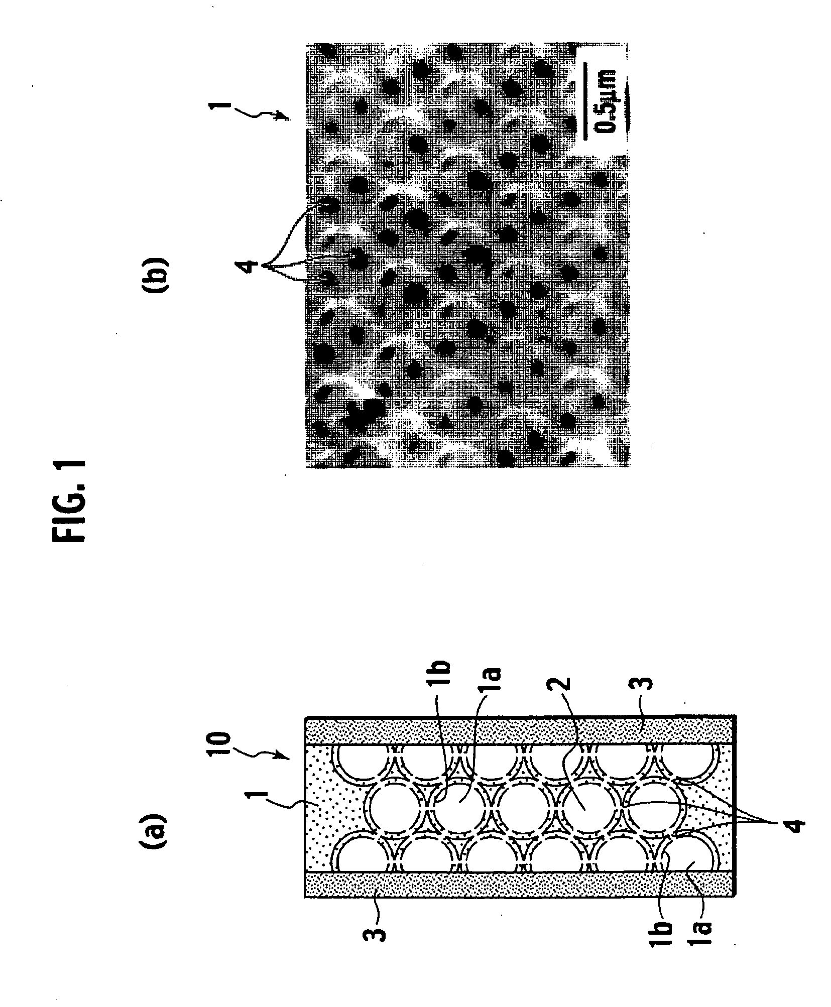
[0075]FIG. 13 shows a fundamental structure of an energy device (fuel cell) applied the ion conductor. The fuel cell (cell) is composed of the electrolyte membrane 10 (ion conductor) including the electrolyte material 2 and formed of the inorganic porous film 1, and pairs of electrodes 3 and gas diffusion layers 5 sandwiching the electrolyte membrane 10 in order. In this case, the silica porous membrane as the inorganic porous film 1, BMImTFSI as the electrolyte material 2, platinum-supported carbon as the electrode 3, and carbon paper as the gas diffusion layer 5 were used, respectively. Each electrode is provided with gas passages 6a using separators 6 so as to be able to supply hydrogen (or fuel gas including hydrogen) and oxygen (or oxidation gas including oxygen). With regard to the electrodes, one side supplying the fuel gas is an anode, and the other side supplying the oxidation gas is a cathode.

[0076]At the power generation from the fuel cell, each gas is supplied t...


PUM

PropertyMeasurementUnit
Diameteraaaaaaaaaa
Diameteraaaaaaaaaa
Percent by volumeaaaaaaaaaa

Abstract

An ion conductor includes: an inorganic porous film which includes multiple fine pores of which surfaces are bonded to multiple proton-donor functional groups; and an electrolyte material which is held in the fine pores of the inorganic porous film, and includes a cation component and an anion component. Further, a method of producing the ion conductor includes: mixing and agitating an inorganic sol, polymer particles, and a solvent; filtering a mixed liquid including the inorganic sol, the polymer particles, and the solvent to fabricate a membrane including the inorganic sol and the polymer particles; removing an extra solvent contained in the membrane formed by filtering, followed by drying the membrane; firing the dried membrane and removing the polymer particles to form an inorganic porous film; chemically modifying to introduce proton-donor functional groups onto surfaces of fine pores of the inorganic porous film; and impregnating the fine pores of the inorganic porous film introduced the proton-donor functional groups with an electrolyte material, followed by drying the inorganic porous film.

Description

TECHNICAL FIELD[0001]The present invention relates to an ion conductor. Specifically, the present invention relates to a composite electrolyte membrane composed of an inorganic porous film holding an electrolyte material in fine pores thereof, and relates to the ion conductor in which the electrolyte material can be improved in ion conductivity when compared with an ionic liquid by itself. Also, the present invention relates to an energy device and a fuel cell using such an ion conductor.BACKGROUND ART[0002]There has been proposed a cation-conductive or proton-conductive ceramic film impregnated with an ionic liquid as an electrolyte membrane for fuel cells (refer to Japanese Patent Translation Publication No. 2004-515351). This film is obtained by being reformed so as to show ion conductivity and treated with the ionic liquid based on a porous and soft ceramic film described in PCT / EP98 / 05939.DISCLOSURE OF INVENTION[0003]However, the conventional electrolyte membrane combined with ...

Claims


Application Information

Patent Timeline
IPC IPC(8): H01M8/00C25B13/04B05D5/12
CPCH01M8/0291Y02E60/50H01M2300/0088H01M8/0289Y02P70/50
Inventor OGAWA, HIROSHITAKEKAWA, TOSHIHIROKANAMURA, KIYOSHI
Owner NISSAN MOTOR CO LTD
Why Eureka
Try Eureka