Lamb-wave resonator and oscillator

a resonator and oscillator technology, applied in the direction of oscillator, impedence network, electrical apparatus, etc., can solve the problems of not revealing specific measures to enhance energy trapping in the widthwise direction, difficult to take full advantage of preferable characteristics, and difficult to say that this electrode design is true, etc., to achieve superior frequency temperature characteristic, low ci value, and high q-value

Inactive Publication Date: 2010-09-23
SEIKO EPSON CORP
View PDF0 Cites 24 Cited by
  • Summary
  • Abstract
  • Description
  • Claims
  • Application Information

AI Technical Summary

Benefits of technology

[0024]According to this aspect of the invention, by adopting the quartz substrate as the piezoelectric substrate, and adopting the Lamb-wave resonator having the optimum substrate thickness and the optimum apposition width...

Problems solved by technology

Therefore, since Lamb waves cannot provide favorable characteristics under design conditions the same as those of Rayleigh waves, a design approach specified for Lamb waves is required.
However, it is hard to say that this electrode design is always optimum because energy trapping in a widthwise direction (a direction perpendicular to the propagation direction of Lamb waves) is not considered.
Further, JP-A-2008-54163 also fails to disclose specific measures to enhance energy trapping in the widthwise direction.
If the vibration leakage occurs in the widthwise direction (a direction perpendicular to the propagation direction of the Lamb wave), i...

Method used


Image

  • Lamb-wave resonator and oscillator
  • Lamb-wave resonator and oscillator
  • Lamb-wave resonator and oscillator

Examples


embodiment

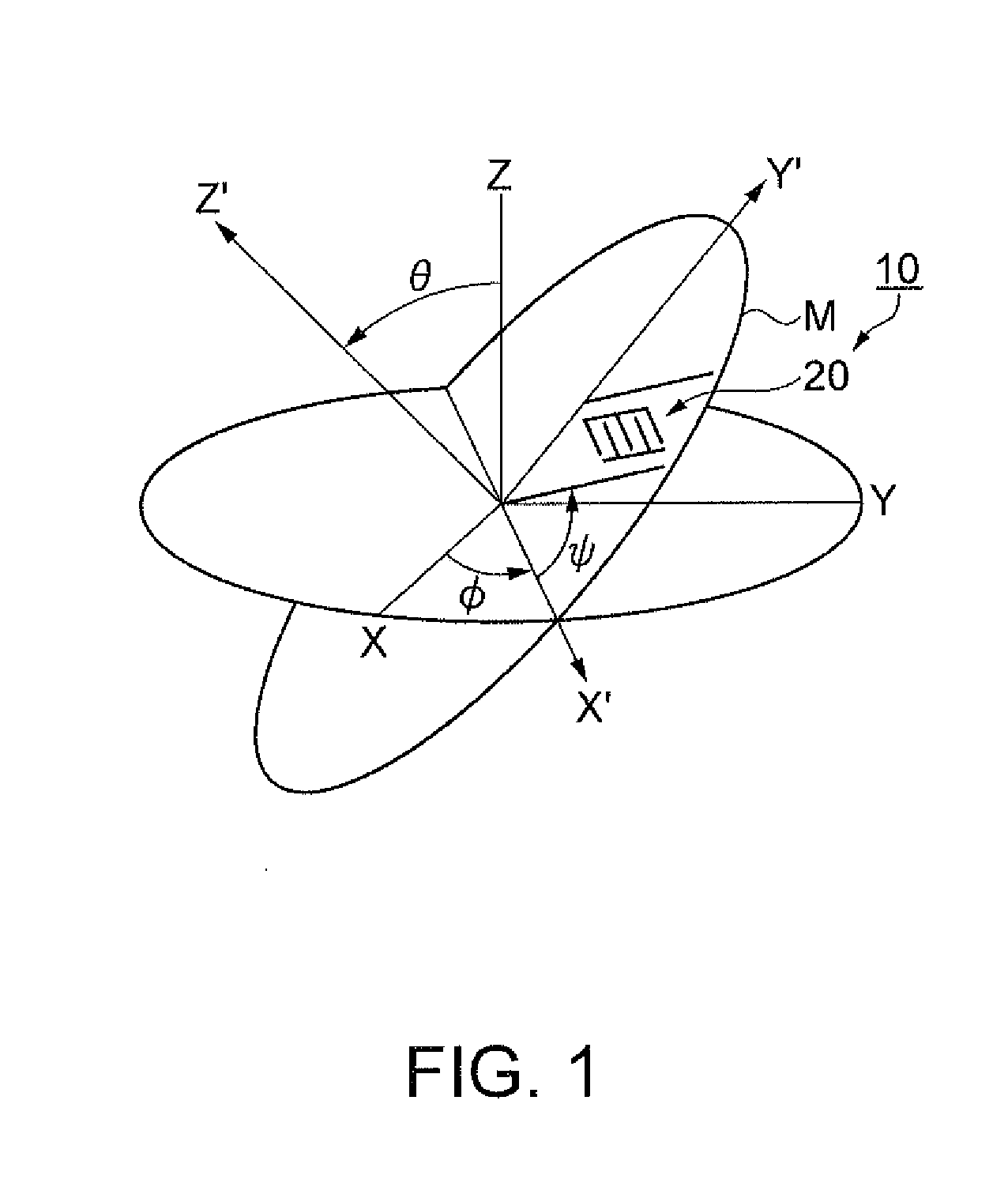
[0053]FIG. 1 is an explanatory diagram showing an azimuth direction in which a quartz substrate is cut out and a direction in which a Lamb wave propagates according to the present embodiment, namely an explanatory diagram of the Euler angles (φ, θ, ψ). The azimuth direction in which the quartz substrate 10 as a piezoelectric substrate is cut out is defined by an X axis called an electrical axis, a Y axis called a mechanical axis, and a Z axis called an optical axis.

[0054]The quartz substrate 10 expressed by the Euler angles (0°, 0°, 0°) forms a Z-cut substrate having a main surface perpendicular to the Z axis. Here, the angle φ in the Euler angles relates to a first rotation of the Z-cut substrate, and represents a first rotation angle assuming that the Z axis is a rotation axis, and the rotation angle in a rotational direction from +X axis to +Y axis is a positive rotation angle.

[0055]The angle θ of the Euler angles relates to a second rotation performed subsequently to the first r...

example 1

[0088]FIGS. 5A through 5C are explanatory diagrams showing a calculation result according to Example 1. In the Example 1, there is shown the case of arranging the Euler angles (0°, 42.0°, 0°), Wi=30λ, Wg=2.0λ, and Wb=28.0λ as an example, and FIG. 5A shows the widthwise displacement distribution of the quartz substrate in the resonant state in the case of arranging the quartz substrate to have an even thickness.

[0089]As shown in FIG. 5A, the displacement becomes the maximum at the center (on the center line P) of the IDT electrode. However, in the areas outside the apposition width Wi and reaching the free surface, the widthwise displacement does not converge, but the displacement in the outer ends of the quartz substrate in the widthwise direction becomes larger. In other words, it shows that the energy is not trapped because of the occurrence of the vibration leakage.

[0090]The occurrence of the vibration leakage to the free surface causes loss of energy, drop of the Q-value as an i...

example 2

[0099]FIGS. 6A through 6C are explanatory diagrams showing a calculation result according to Example 2. In the Example 2, there is shown the case of arranging the Euler angles (0°, 42.0°, 0°), Wi=20λ, Wg=6.0λ, and Wb=30.0λ as an example, and FIG. 6A shows the widthwise displacement distribution of the quartz substrate in the resonant state in the case of arranging the quartz substrate to have an even thickness.

[0100]As shown in FIG. 6A, in the case of arranging the thickness of the quartz substrate to be even, the widthwise displacement does not converge in the area outside the apposition width Wi and reaching the free surface, and the displacement in the outer ends of the quartz substrate in the widthwise direction becomes larger. In other words, it shows that the energy is not trapped because of the occurrence of the vibration leakage.

[0101]FIG. 6B shows the case of arranging the thickness tg in the gap area (Wg) of the quartz substrate to be smaller than the thickness ti thereof ...


PUM


Abstract

A Lamb-wave resonator includes: a piezoelectric substrate; an IDT electrode disposed on one principal surface of the piezoelectric substrate, having bus bar electrodes each connecting one ends of a plurality of electrode finger elements, the other ends of the plurality of electrode finger elements being interdigitated with each other to form an apposition area; and a pair of reflectors disposed on the one principal surface of the piezoelectric substrate, and respectively arranged on both sides of the IDT electrode in a propagation direction of a Lamb wave, wherein denoting a thickness of the piezoelectric substrate in the apposition area of the electrode finger elements as ti, a thickness of the piezoelectric substrate in areas between respective ends of the apposition area in a direction perpendicular to the propagation direction of the Lamb wave and the bus bar electrodes as tg, and a wavelength of the Lamb wave as λ, the thickness ti exists in a range represented by 0<ti/λ≦3, and a relationship of tg<ti is satisfied.

Description

BACKGROUND[0001]1. Technical Field[0002]The present invention relates to a Lamb-wave resonator and an oscillator equipped with the Lamb wave resonator.[0003]2. Related Art[0004]A Lamb wave is a plate wave, which is a bulk wave propagates inside a substrate while being repeatedly reflected by upper and lower surfaces of the substrate in the case in which the substrate is arranged to have a thickness equal to or smaller than several wavelengths of the wave to be propagated. In contrast to a surface wave having 90% of the energy thereof in areas with a depth of within one wavelength from the surfaces of the substrate, such as a Rayleigh wave, a leaky surface acoustic wave, or a quasi longitudinal leaky surface acoustic wave, the Lamb wave is a bulk wave propagating inside the substrate, and therefore, the energy thereof is distributed throughout the entire substrate.[0005]According to “Ultrasonic Wave Handbook” edited by Ultrasonic Wave Handbook Editorial Committee, published by Maruze...

Claims


Application Information

Patent Timeline
IPC IPC(8): H03B5/32H03H9/17
CPCH03H9/02551H03H9/02228
Inventor TANAKA, SATORU
Owner SEIKO EPSON CORP
Why Eureka
Try Eureka