
Method and system for producing glass, in which chemical reduction of glass components is avoided

a technology of glass components and glass cylinders, applied in glass rolling apparatus, manufacturing tools, furnaces, etc., can solve the problems of uneconomic production, unfavorable production, and reduced production efficiency in conventional systems, and achieve the effect of reducing the reduction-sensitive components of glass and high refractive index

Inactive Publication Date: 2010-09-30
SCHOTT AG
View PDF28 Cites 36 Cited by
  • Summary
  • Abstract
  • Description
  • Claims
  • Application Information

AI Technical Summary

Benefits of technology

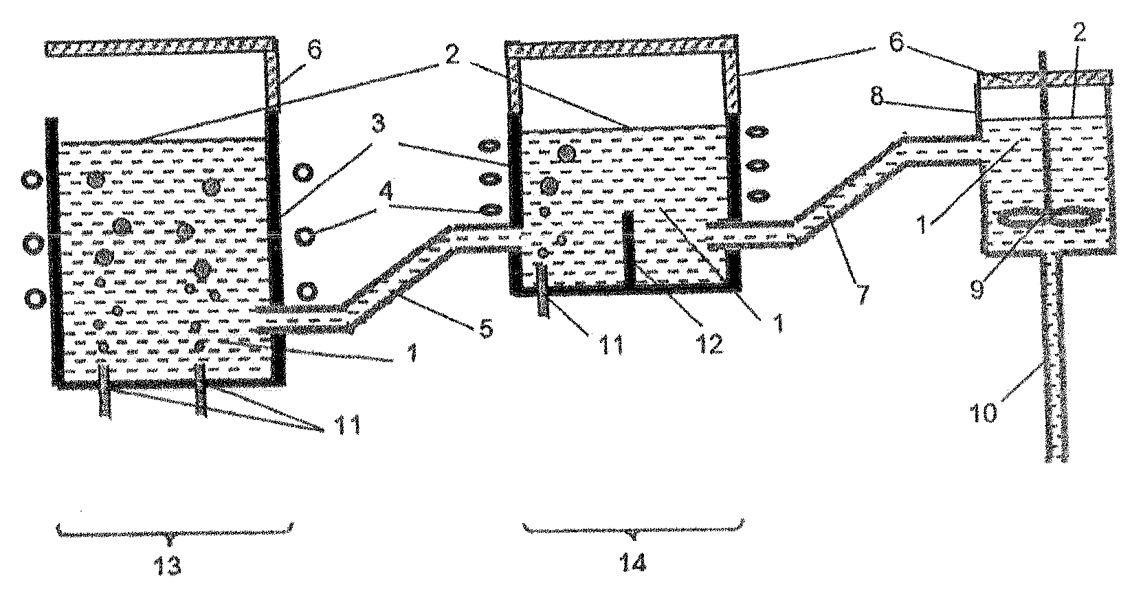
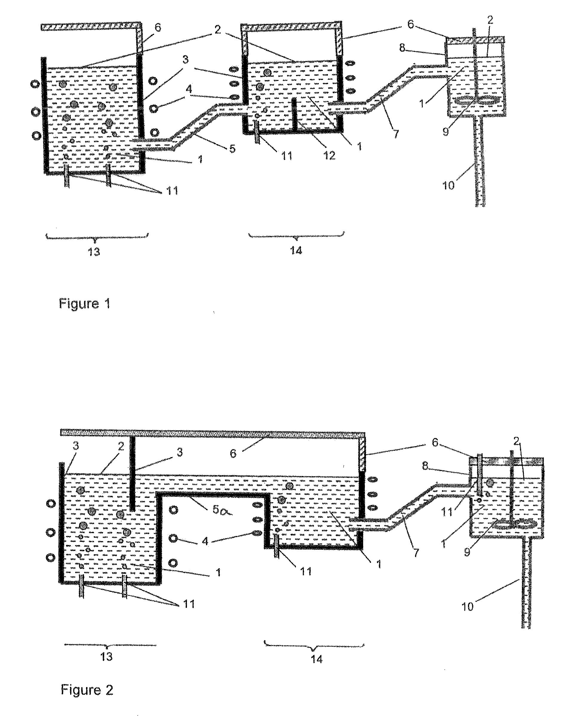
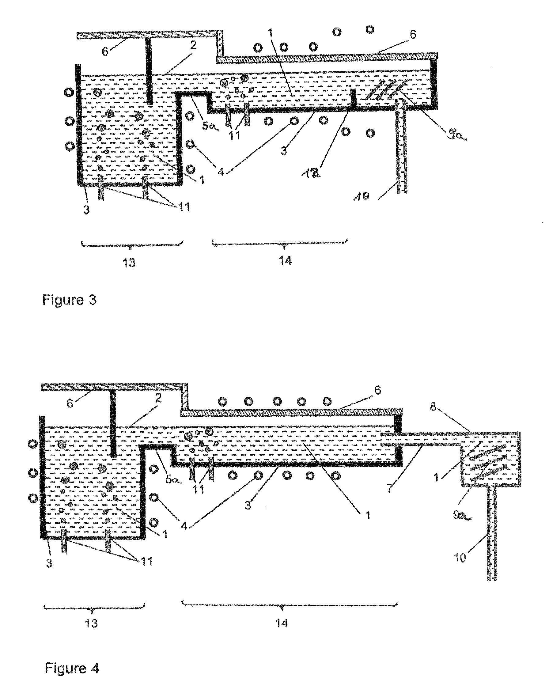
The present invention provides an apparatus for producing glass with reduced reduction-sensitive components. This is achieved by introducing or injecting oxidizing agents into the fining vessel and / or melt crucible, where the oxidizing agents prevent the reduction of sensitive components. The apparatus includes a means for conducting the oxidizing agents into the fining vessel and melt crucible. The melt is heated using electrodes or high-frequency radiation, and the refractive index is controlled through the use of oxygen and / or ozone. The apparatus also includes a cooling system for the melt vessels, which prevents the reduction of the melt and the formation of a skull-crust aggressive attack on the melt. The melt is then transferred to a fining vessel for further processing. The invention provides a method for producing glass with high refractive index and good transmission values.

Problems solved by technology

Many high-index materials and glass, especially those used for optical, fiber-optic and display-applications as well as for applications for protection and passivation of electronic parts and components, are composed so that the melt technical production leads to a considerable loss of performance in conventional systems and facilities concerning very important properties for the particular application such as transmission, refractive index position, uniformity, electrical resistance and compressibility, thus rendering the production uneconomical.
These lead to absorption of light in the visible spectral region and, thus, to discoloration.
If the precipitated particles or crystals grow, tension and defects occur in the material that can during irradiation with high energy-densities (for example: lasers) lead to destruction of the glass.
The described process is also highly dangerous in connection with free phosphate (P2O5), because it can lead to explosive reactions.
In the case of platinum elements this is connected with a discoloration and a worsening of the transmission properties.
The use of so-called flameproof materials having an oxidic or oxidic-ceramic basis, for example, zirconium, silicate, or aluminium oxide material, only solves a part of the above-described problems and is additionally not an economically reasonable solution, either.
But when they are attacked by the melt they dissolve in part and are “bad-natured”, that is these flameproof materials can lead to faults in the glass.
Especially aggressive attack of high-index melt compositions that should additionally be workable by precise pressing is not acceptable, because the dissolution of the crucible and the entry of the material into the melt lead to unwanted changes in properties of the materials and glasses, especially an increase in the transformation temperature, changes in viscosity properties, changes in refractive index and Abbe number as well as changes in transmission.
As a further effect of the strong aggressive attack on flameproof materials, apart from the considerable worsening of properties and uniformity of the glass, an in part extreme shortening of the dwell time of the melt equipment arises causing extensive costs.
On the one hand costs arise because of the need to renew the melt unit and on the other hand because of repeated downtime costs.
Because of the high reduction potential and the comparatively high temperatures that are needed for injection and melting of high-index melts, especially in the niobium oxide / phosphorous oxide system, none of the cited documents offers the potential to produce the claimed glasses in the necessary quality and with the necessary properties.

Method used


Image

  • Method and system for producing glass, in which chemical reduction of glass components is avoided
  • Method and system for producing glass, in which chemical reduction of glass components is avoided
  • Method and system for producing glass, in which chemical reduction of glass components is avoided

Examples


example 1

[0079]A glass of the following composition was produced:

P2O5: 21.0%

ΣNb2O5, Ta2O5, Sb2O3: 50.5%

ΣMgO, CaO, SrO, BaO: 19.0%

ΣLi2O, Na2O, K2O, Rb2O, Cs2O: 4.5%

ΣZnO, TiO2: 5.0%

[0080]A melting skull crucible and a fining skull crucible consisting of AlMgSi1, connection segment, homogenization unit, agitator and feeder consisted of PtIr1 were used in the process.

[0081]The following melting parameters were used:

Melting: 1200° C.-1210° C., O2-Bubbling: 3×50 l / h

Fining: 1220° C.-1230° C., O2-Bubbling: 2×20 l / h

Mixing: 1180° C.

Feeder: 1150° C.

[0082]Ingots were produced.

[0083]The following optical values were measured:

nd=1.92773;

vd=20.61;

ΔPg,F=−0.0312

[0084]τi (400 nm; 25 mm)=0.104; 0.0021; 0.1152

τi (420 nm; 25 mm)=0.435; 0.2321; 0.4952

τi (460 nm; 25 mm)=0.812; 0.7481; 0.8462

τi (500 nm; 25 mm) 0.898; 0.8581; 0.9322

[0085]The given reference values (1) have been measured in a glass of the same composition that has been melted in a melting skull crucible made of AlMgSi1 at 1210° C. and fined in a ...

example 2

[0087]A glass of the following composition was produced:

P2O5: 22.8%

ΣNb2O5, Ta2O5, Sb2O3: 47.0%

ΣMoO3, WO3: 14.0%

ΣMgO, CaO, SrO, BaO: 2.0%

ΣLi2O, Na2O, K2O, Rb2O, Cs2O: 9.2%

ΣTiO2, GeO2: 5.0%

[0088]A melting skull crucible and a fining skull crucible consisting of AlMgSi1, connection segment, cooling duct, homogenization unit, agitator and feeder consisted of PtIr1 were employed in the process.

[0089]The following melting parameters were adjusted:

Melting: 1110° C.-1120° C., O2-Bubbling: 3×30 l / h

Fining: 1130° C.-1150° C., O2-Bubbling: 2×150 l / h

Mixing: 1110-1120° C.

Feeder: 1100° C.

[0090]Ingots were produced.

[0091]The following optical values were measured:

nd=1.97242;

vd=22.65;

ΔPg,F=0.0223

[0092]τi (400 nm; 25 mm)=0.070 (0.06)

τi (420 nm; 25 mm)=0.423 (0.36)

τi (500 nm; 25 mm)=0.875 (0.668)

[0093]The reference values given in brackets have been measured in a glass of the same composition that has been melted in a melting skull crucible made of AlMgSi1 at 1120° C. and fined in a conventional finin...

example 3

[0094]A glass for optical and electronic purposes of the following composition was produced:

ΣB2O3, SiO2: 10.5%

ΣSb2O3, Bi2O3: 77.0%

ΣMgO, CaO, ZnO: 12.5%

[0095]A melting skull crucible, connection segment, cooling duct and feeder consisting of PtIr1 were used.

[0096]The following melting parameters were adjusted:

Melting: 1000° C.-1050° C., O2-Bubbling: 3×50 l / h

[0097]Cooling track: 900-950° C.

Feeder: 850° C.

[0098]Glass flakes were produced.

[0099]The following optical values were measured:

nd=2.101


PUM

PropertyMeasurementUnit
widthsaaaaaaaaaa
widthsaaaaaaaaaa
slit widthsaaaaaaaaaa

Abstract

In the apparatus for producing glass reduction of reduction-sensitive components in the glass melt is reduced or preferably is prevented during the melting and / or fining processes by introducing an oxidizing agent into the glass melt. The apparatus has a melt crucible, a fining vessel, and a device for conducting oxygen and / or ozone into the glass melt in the melt crucible and / or fining vessel, in order to suppress reduction of reduction-sensitive components of the glass melt. A preferred embodiment of the apparatus has a metallic skull crucible, which includes the melt crucible and / or the fining vessel. The apparatus preferably includes a homogenization unit connected to the fining vessel to receive glass melt from the fining vessel in order to further process the glass melt after refining.

Description

CROSS-REFERENCE[0001]This is a divisional, filed under 35 U.S.C. 120, of U.S. patent application Ser. No. 11 / 835,689, which was filed Aug. 8, 2007 in the U.S.A. The subject matter of this divisional application is also disclosed, at least in part, in German Patent Application DE 10 2006 037 828.8, which was filed in Germany on Aug. 12, 2006, and in DE 10 2007 008 299.3-45, which was filed in Germany on Feb. 16, 2007. The subject matter of the foregoing German Patent Applications, which provide the basis for a claim of priority of invention under 35 U.S.C. 119 (a) to (d), is hereby incorporated herein by explicit reference thereto.BACKGROUND OF THE INVENTION[0002]1. The Field of the Invention[0003]The present invention relates to a method and an apparatus for producing glass, in which the reduction of reduction-sensitive components of the glass is decreased and preferably is avoided during the melting and fining process. The glass is preferably glass with a high refractive index. Acc...

Claims


Application Information

Patent Timeline
Patent Type & Authority Applications(United States)
IPC IPC(8): C03B5/18C03B17/00
CPCC03B5/021C03B5/027C03C3/00C03B2211/70C03B5/193C03B5/173C03B5/18C03B5/225
Inventor RITTER, SIMONE MONIKAWOLFF, SILKE
Owner SCHOTT AG
Learn More