[0007]Spatially
selective excitation is a technology that is widely used in
magnetic resonance imaging for spatially delimiting the transverse magnetization that is generated during excitation and / or spatially varying its amplitude and phase in the excitation volume in accordance with predetermined distributions. For
slice selection, which is the most frequent case of spatial
selective excitation, the excitation volume is reduced to a predetermined slice. Multi-dimensional spatially
selective excitation, in which the excitation volume is delimited in more than one direction and / or the excitation is modulated in more than one direction, has also produced numerous applications. These include excitation of a small three-dimensional volume within a substantially larger object under investigation for localized
spectroscopy, imaging of a selectively excited region (ROI:
region of interest) with reduced
field of view (FOV) with the aim of reducing the measuring time or improving the resolution, excitation of special volumes that are adjusted to the structures of the object under investigation or also echo-
planar imaging with reduced echo
train lengths. The amplitude and
phase modulation of transverse magnetization can also be used during excitation to compensate for disadvantageous effects of an inhomogeneous magnetic transmission field (B1 field) of the RF antennas used for excitation. This is an application that has become immensely important these days due to the strong increase in
high field MRI systems which often involve inhomogeneities of this type.
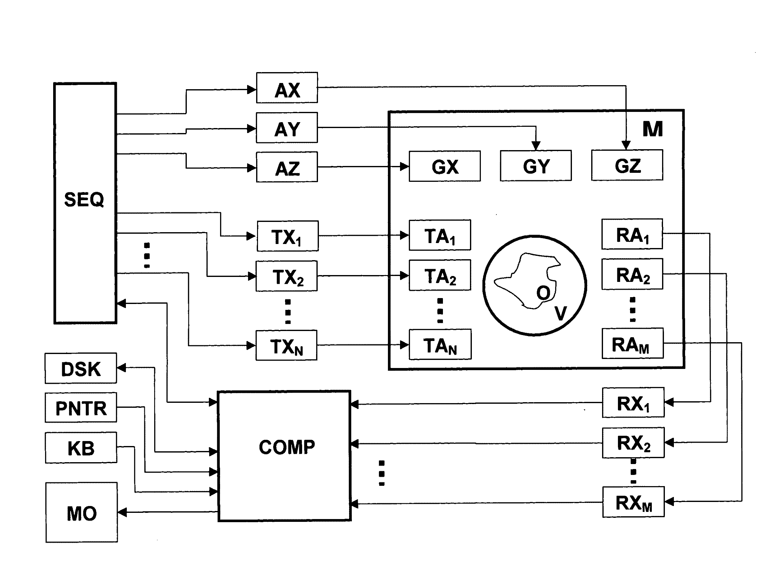
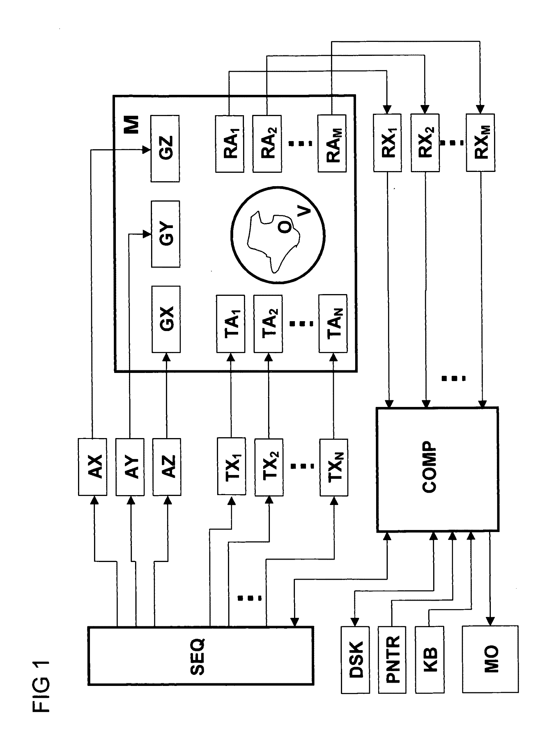
[0008]Spatially selective excitation was conventionally performed by means of one single RF transmitting antenna with a substantially homogeneous transmission field (B1 field) in combination with the
gradient system. Inspired by the success of
parallel imaging, in which the signals are recorded with an arrangement of several RF receiving antennas, which is also called an
antenna array in
technical literature and which consists of several individual antennas or elements, one has started in the meantime to also use such antenna arrays, which consist of several elements and are operated on several
RF transmission channels of the MR measuring system, for transmission with selective excitation. It is thereby possible to partially replace
spatial encoding, which is realized for selective excitation analogously to acquisition by variation of gradient fields, by so-called
sensitivity encoding and thereby reduce the length of the excitation pulses. One thereby utilizes the information which is contained in the different spatial variations of the transmission fields of the individual array elements (also called transmission profiles below). Since the length of such selective excitation pulses was in most cases one of the limiting criteria for the applicability of this technology, the so-called
parallel excitation (PEX) or multi-channel excitation is a promising approach to use spatially selective excitation on an even wider basis than before.
Spatial encoding during the transmission of RF pulses for selective excitation is called transmission
spatial encoding below in order to distinguish it from
spatial encoding during acquisition.
[0009]One of the basic tasks in connection with the use of selective excitation is the determination of the RF pulses that must be irradiated by the
RF transmission system of the MR measuring system in order to generate the desired distribution of transverse magnetization in combination with additional magnetic fields. In the article “A k-space analysis of small tip-angle excitation” [1] Pauly et al. describe a method for single-channel spatially selective excitation by means of which the searched pulse form B1(t) can be calculated on the basis of a mathematical analogy between selective excitation and Fourier imaging substantially by Fourier transformation of the desired transverse magnetization distribution and scanning of the
Fourier transform along a predetermined k-space trajectory. Katscher et al. extended this calculation method for the case of an
antenna array having several independent transmission channels [2].
[0010]An object often contains several nuclear spin species having different
precession frequencies, as is the case for nuclei of different chemical elements or similar nuclei in different chemical environments. The nuclear spin species can be combined into nuclear spin ensembles of the same Larmor frequency which each contribute to the overall transverse magnetization. Since the RF pulses determined according to Pauly et al. or Katscher et al. are, in general, optimum with respect to the realization accuracy of the desired transverse magnetisation distribution only for nuclear
spins that precess at a determined frequency, these RF pulses excite different, generally unintentional distributions for transverse magnetization contributions of the individual nuclear spin ensembles. For this reason, Meyer et al. [3] or Setsompop [4] present e.g. methods that also allow spatially selective excitation for nuclear spin ensembles with a selected
precession frequency. This case is called spatially spectrally selective excitation using spatially spectrally selective RF pulses. This approach also allows to predetermine individual distributions, which may be different or identical, for the transverse magnetization contributions of the individual nuclear spin ensembles, and excite them with one or several RF pulses. The terms spatially selective excitation or selective excitation are also used below unless the spectral selectivity is to be particularly emphasized.
[0011]The basis for the
calculation methods of the RF pulses used for selective excitation are, in general, the well-known Bloch equations for describing the development of the magnetization in an object under the influence of external magnetic fields. Restricting to the case in which external fields deflect the sample magnetization out of the equilibrium state (z direction) through small angles only (called the small tip angle approximation below), the distribution of the transverse magnetization in the x-y plane, described as a complex variable, can be calculated according to the following equation (thereby neglecting relaxation effects):Mxy(x)=γM0∑nNSn(x)∫0TB1,n(t)ϕ(x,t)t(1)
[0012]Mxy is the generated transverse magnetization distribution, x designates the spatial coordinate, γ defines the gyromagnetic ratio of the investigated spin species, M0 is the equilibrium magnetization (the magnetic base field is oriented in the z direction), B1,n is the RF pulse supplied to the transmitting antenna n by N, Sn is the spatial variation of the transmission field of
array element n, φ is the phase that accumulates in the transverse magnetization from the time of generation to termination of the influence of the additional magnetic fields, and T is the duration of the longest one of the N RF pulses. Mxy and B1,n are complex variables, the real and imaginary parts of which describe the x or y components of the respective
vector size in the coordinate system that rotates with the RF pulses (vectorial variables are in bold print).

