Low noise cascode amplifier

Active Publication Date: 2010-10-21
NAT TAIWAN UNIV
View PDF7 Cites 11 Cited by
  • Summary
  • Abstract
  • Description
  • Claims
  • Application Information

AI Technical Summary

Benefits of technology

[0011]It is a feature of the present invention to provide a low noise cascode amplifier, wherein the cascode device comprises at least o

Problems solved by technology

Although the MOS M1 can be used to amplify the input signal, the resulting gain is always too low to be a fine amplifier, and leads to the limited application of the amplifier.
Although the triple cascode device 20 provides the above adv

Method used


Image

  • Low noise cascode amplifier
  • Low noise cascode amplifier
  • Low noise cascode amplifier

Examples


Example

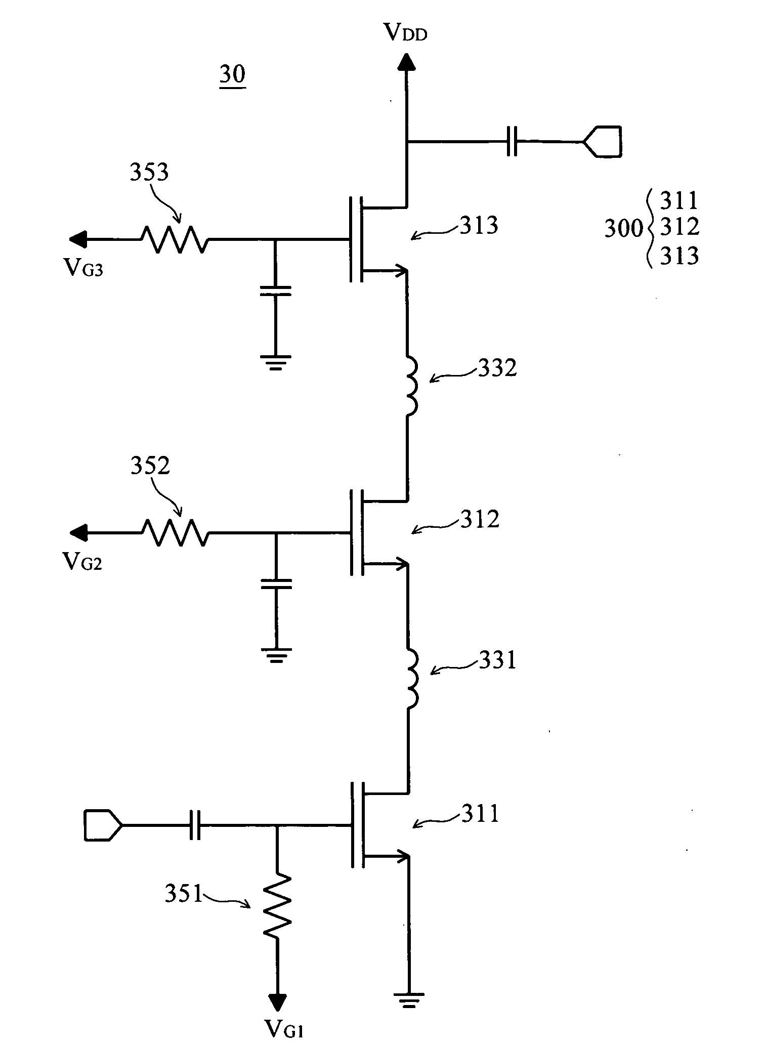
[0027]Referring to FIG. 6, disclosed is a circuit diagram for a low noise cascode amplifier according to an embodiment of the present invention. The low noise cascode amplifier 30 comprises a first transistor 311, a second transistor 312, a third transistor 313, a first inductor 331, and a second inductor 332, wherein the noise figure can be reduced via the application of the inductors.

[0028]The series connection of the first transistor 311, the second transistor 312, and the third transistor 313 can form a cascode device, such as a triple cascode device 300. The triple cascode device 300 is usually provided within various kinds of amplifiers, because of the advantages associated with high input impedance, high output impedance, high gain, and compact size.

[0029]However, the triple cascode device 300 cannot be considered a suitable low noise amplifier (LNA) for a wireless transceiver due its high noise figure. In the embodiment of the invention, the cascode device comprises at least...


PUM


Abstract

The present invention relates to a low noise cascode amplifier comprising a first transistor, a second transistor, a third transistor, a first inductor, and a second inductor. Furthermore, the first transistor can connect with the second transistor via the first inductor, and the second transistor can connect with the third transistor via the second inductor; thereby, a cascode device can be formed. The inductor and the parasitic capacitances can resonate at high frequency, so that the noise figure of the cascode amplifier can be reduced.

Description

BACKGROUND OF THE INVENTION[0001]1. Technical Field[0002]The present invention generally relates to cascade amplifier, and more particularly to low noise cascade amplifier.[0003]2. Description of the Prior Art[0004]The integrated circuit always comprises an amplifier circuit for amplifying an input signal. In general, the metal-oxide semiconductor device (MOS) or the cascode can be the amplifier circuit. Referring to FIG. 1, what is shown is a circuit diagram for the MOS as an amplifier according to the prior art. The amplifier comprises a MOS M1 and a current source I, wherein the source of the MOS M1 is grounded, the gate of the MOS M1 connects to a bias voltage VI, and the drain of the MOS M1 connects to the current source I to form a common source MOS. Although the MOS M1 can be used to amplify the input signal, the resulting gain is always too low to be a fine amplifier, and leads to the limited application of the amplifier.[0005]Referring to FIG. 2, what is shown is a circuit ...

Claims


Application Information

Patent Timeline
IPC IPC(8): H03F1/22H03F3/16
CPCH03F1/223H03F2200/61H03F2200/294H03F1/26
Inventor HUANG, BO-JRWANG, HUEI
Owner NAT TAIWAN UNIV
Why Eureka
Try Eureka