System for dehydrating natural gas

a technology of natural gas and dehydration system, which is applied in the direction of gaseous fuels, separation processes, fuels, etc., can solve the problems of many problems in pipeline processing equipment, environmental problems, and natural gas found at the wellhead, and achieve the effect of reducing the amount of make-up fuel needed and reducing costs

Inactive Publication Date: 2010-11-11
GLY TECH SERVICES
View PDF18 Cites 11 Cited by
  • Summary
  • Abstract
  • Description
  • Claims
  • Application Information

AI Technical Summary

Benefits of technology

[0017]It is still a further object of the invention to provide a system of natural gas dehydration that allows an operator to reduce costs associated with the natural gas processing.
[0018]These and other objects of the invention are achieved through a provision of an apparatus and process for dehydrating a wet natural gas while removing volatile organic compounds (VOCs). The well-produced wet natural gas is contacted with a dehydrating agent, such as glycol, which absorbs water from the natural gas. The mixture of dehydrating agent / water and heavy hydrocarbons is conveyed through a heat exchanger, separator and reboiler for removing VOCs and recovering the dehydrating agent for recirculation. A stripping column is coupled to an outlet of the reboiler for stripping the dehydrating agent of any traces of water that is flashed out in the reboiler. Light hydrocarbons removed from the mixture are re-circulated as flash gas in the reboiler, thereby reducing the amount of make-up fuel necessary in the heating process.

Problems solved by technology

However, natural gas found at the wellhead, although still composed primarily of methane, is by no means as pure.
Impurities in natural gas, particularly water, can cause many problems in pipeline processing equipment.
This presents an environmental problem.
The control of BTEX emissions is one of the largest environmental challenges facing the U.S. natural gas industry.
However, the removal of water vapor that exists in solutions in natural gas process requires a more complex treatment.
The incineration systems have high operating costs and do not recover any hydrocarbons for sales.
Problems with this system include the initial cost of the complex array of bubble caps themselves, the inability of the system to recover and thus use the BTEX and other components that are carried off by the stripping gas, and the stripping gas required is often more than can be used as fuel, the excess being flared which adds to waste of material.

Method used


Image

  • System for dehydrating natural gas
  • System for dehydrating natural gas

Examples


Embodiment Construction

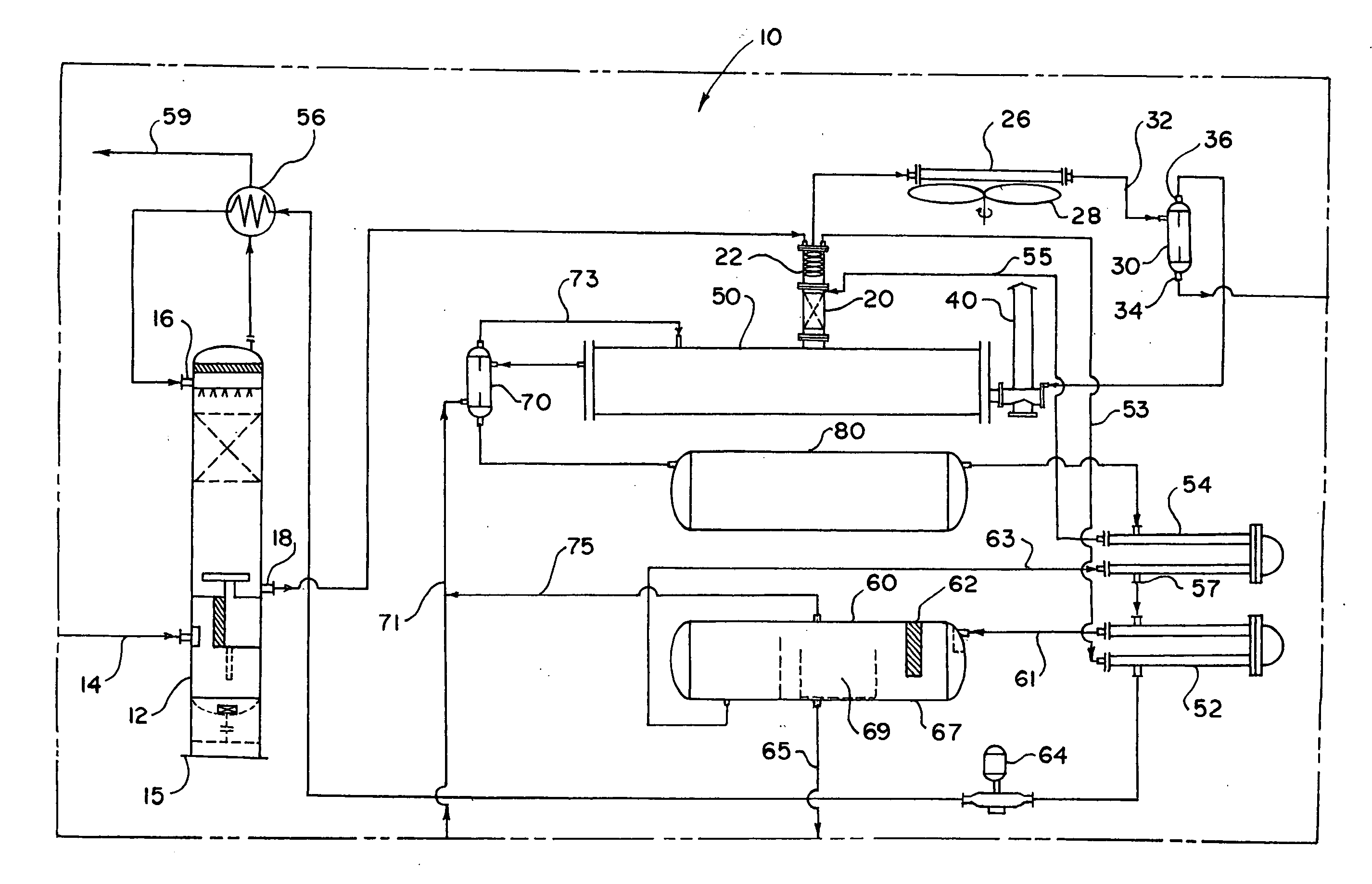
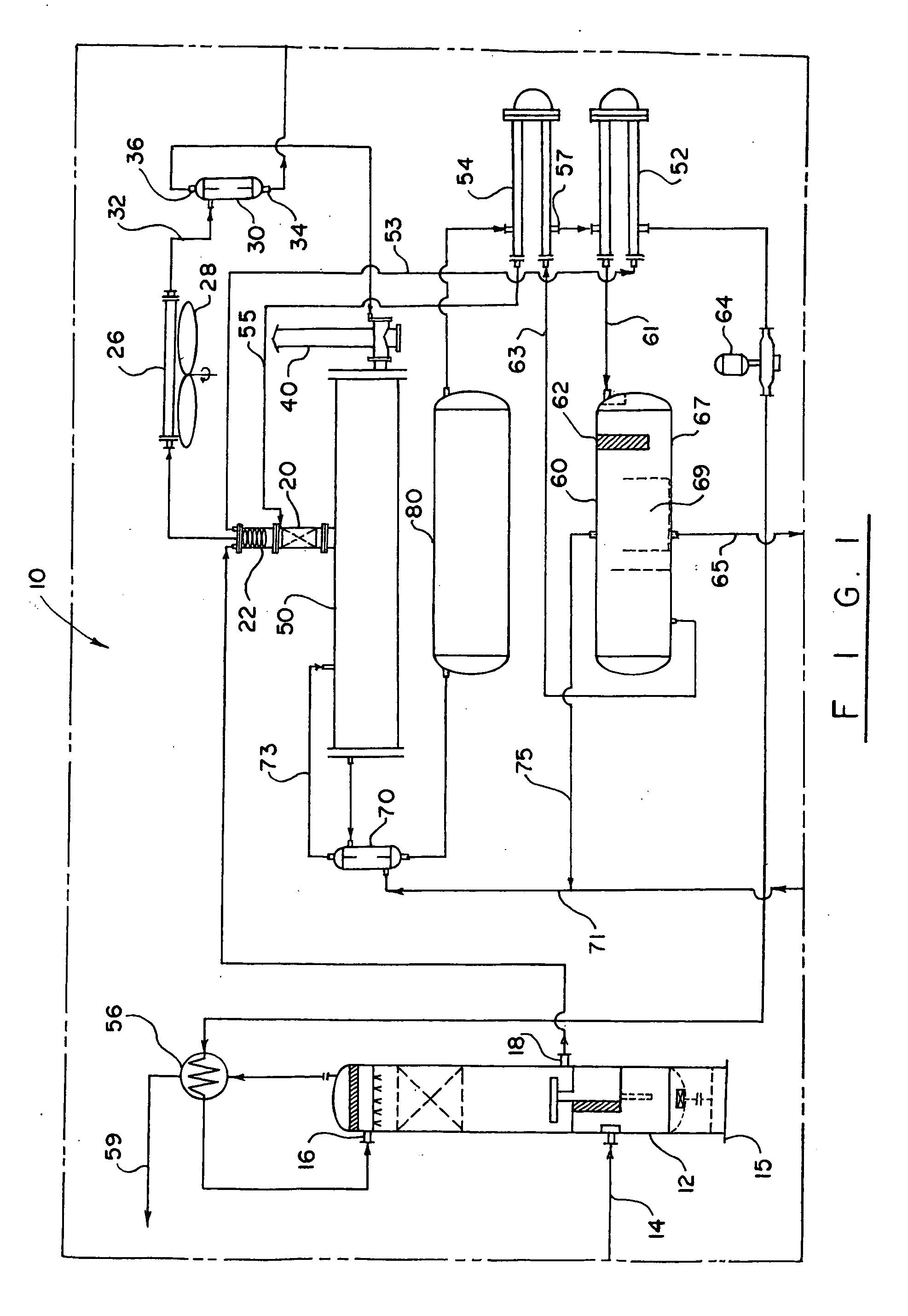
[0021]Turning now to the drawing in more detail, numeral 10 designates the system of natural gas dehydration according to this invention. The system 10 comprises a contactor 12, which receives wet natural gas from a ground well (not shown) through a suitable conduit 14. The contactor 12 has a multistage-type design. If necessary, the contact tower 12 can be mounted on a skid 15 to facilitate transportation of the contact tower to an in-situ location.

[0022]In the illustrated embodiment, the wet natural gas is introduced into the contactor 12 at a lower location and flowed up through the contactor 12 against an oppositely traveling dehydrating agent, such as glycol, which has been introduced at an upper location of the contactor 12 through an inlet 16. At this stage, the wet natural gas is pressurized to the pressure of the ground well, arriving in the contactor 12, for the purpose of this description, at 900-1000 p.s.i and temperature of about 100° F. This invention works well with o...


PUM

PropertyMeasurementUnit
temperatureaaaaaaaaaa

Abstract

An apparatus and process for dehydrating a wet natural gas while removing volatile organic compounds (VOC). The well-produced natural gas is contacted with a dehydrating agent, such as glycol, which absorbs water from the natural gas. The mixture of dehydrating agent/water and heavy hydrocarbons is conveyed through a heat exchanger, separator and reboiler for removing VOC and recovering the dehydrating agent for recirculation. A stripping column is coupled to an outlet of the reboiler for stripping the dehydrating agent of any traces of water that is flashed out in the reboiler. Light hydrocarbons removed from the mixture are re-circulated as flash gas in the reboiler, thereby reducing the amount of make-up fuel necessary in the heating process.

Description

BACKGROUND OF THE INVENTION[0001]The present invention relates generally to an apparatus and process for use with natural gas dehydrators, and more particularly to a system of glycol dehydration of natural gas.[0002]Natural gas used by consumers is composed almost entirely of methane. However, natural gas found at the wellhead, although still composed primarily of methane, is by no means as pure. Gas wells produce raw natural gas by itself, while condensate wells produce free natural gas along with the semi-liquid hydrocarbon condensate. Whatever the source of the natural gas, once separated from crude oil (if present) commonly exists in mixtures with other hydrocarbons, principally ethane, propane, butane, and pentanes. In addition raw natural gas contains water vapor, hydrogen sulfide (H2S), carbon dioxide, helium, nitrogen, and other light and heavy hydrocarbon compounds, as well as various hazardous materials, such as benzene, toluene, ethylbenzene and xylene (BTEX) and other vo...

Claims


Application Information

Patent Timeline
Patent Type & Authority Applications(United States)
IPC IPC(8): C01B3/50B01J8/00
CPCB01D53/263C10L3/10B01D2258/06B01D2257/708Y02A50/20
Inventor LOGUE, ALLEN J.
Owner GLY TECH SERVICES
Why Eureka
Try Eureka