High throughput finishing of metal components

Active Publication Date: 2010-11-18
REM TECHNOLOGY INC
View PDF24 Cites 8 Cited by
  • Summary
  • Abstract
  • Description
  • Claims
  • Application Information

AI Technical Summary

Benefits of technology

[0015]The present invention addresses these problems by providing a method for finishing a surface of a metal component, comprising: providing a receptacle containing a quantity of non-abrasive media sufficient to substantially immerse a part of the component on which the surface is located; providing a quantity of finishing chemistry capable of forming a relatively soft conversion coating on the surface; immersing the component at least partially into the media; flooding the receptacle with an excess of the chemistry such that the surface is essentially immersed in the chemistry; and inducing high energy relative movement between the surface and the media in order to co

Problems solved by technology

It will be understood that once the component begins to agitate the media

Method used


Image

  • High throughput finishing of metal components
  • High throughput finishing of metal components
  • High throughput finishing of metal components

Examples


Example

Example 1

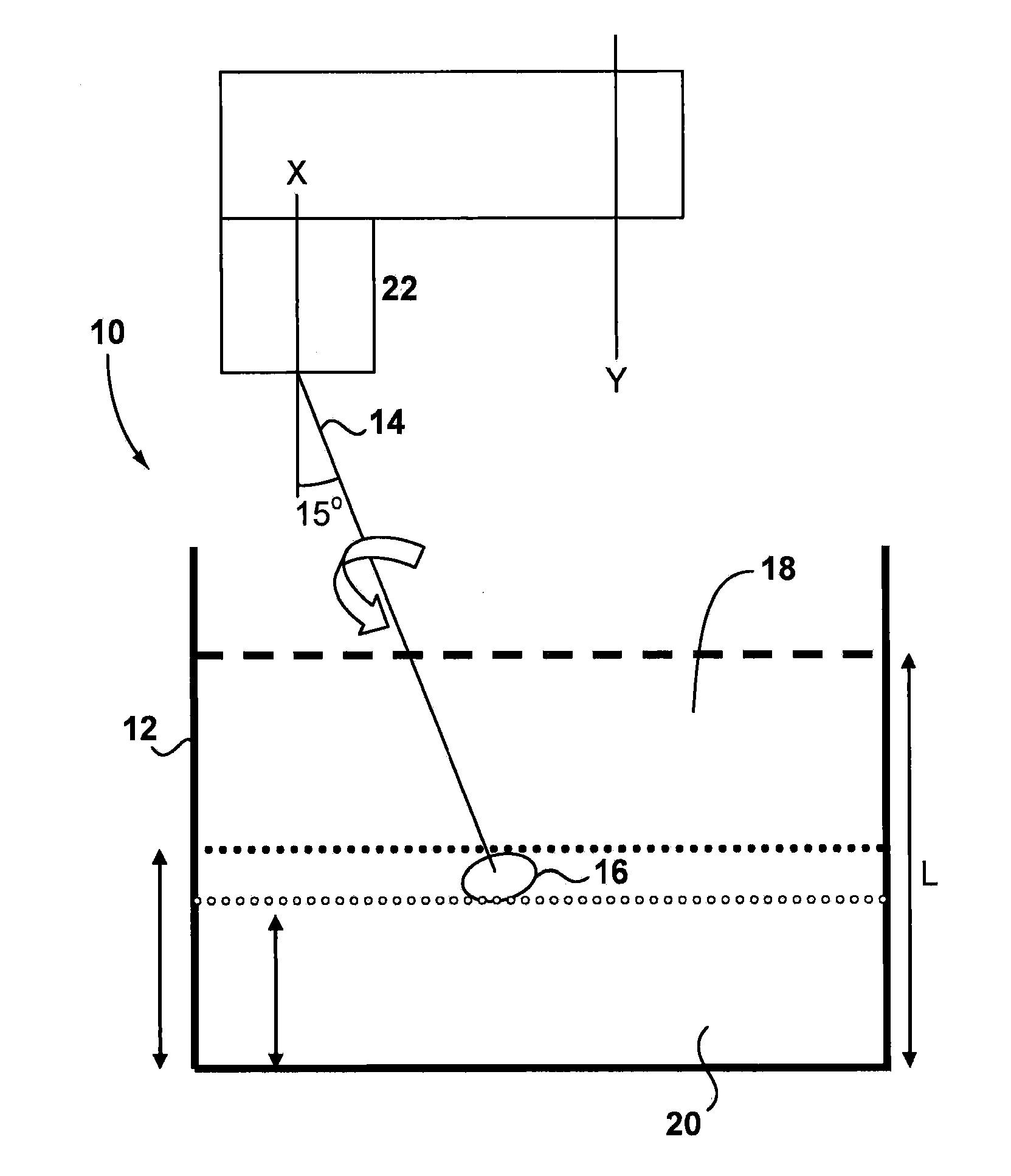
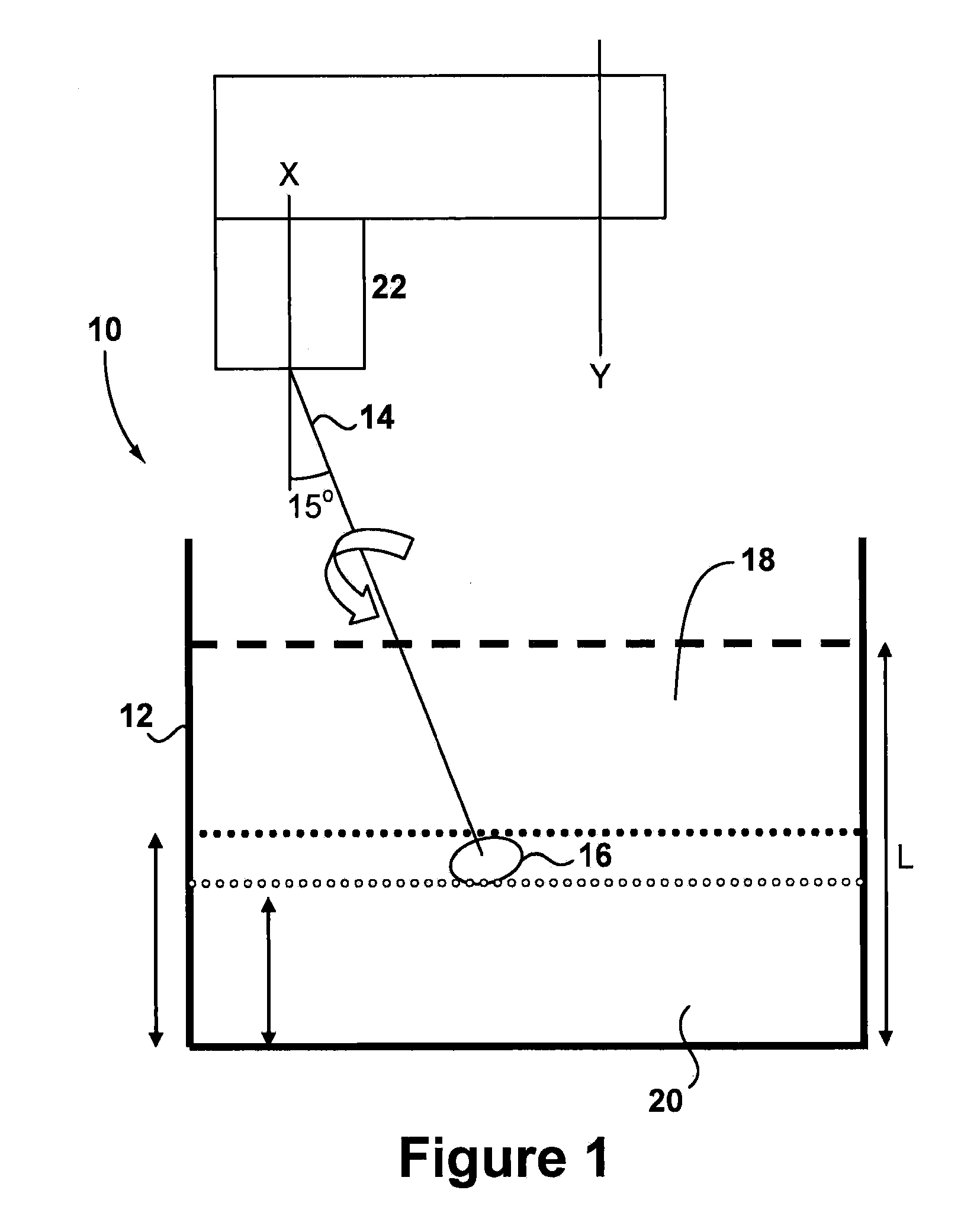
[0052]In a first example, the bowl 12 was filled with media 18 to a level of approximately 406 mm depth. The media comprised non-abrasive 3×5 SCT (straight cut triangles). A quantity of 76 litres of chemistry of type FERROMIL® FML-7800 diluted at 35 vol % and pre-heated, was added to the bowl. The media was stirred and then the chemistry was drained, leaving the media wet and at a temperature of around 43° C. (all temperature was measured using an infra-red heat sensor gun reading off the top of the media). A rear axle hypoid ring gear of 23 cm diameter was attached to the spindle 14 and lowered into the bowl to a depth at which the bottom of the ring gear was around 160 mm from the bottom of the bowl. The gear had an initial surface finish of 1.2-1.7 microns. The turret 22 was driven for 10 minutes at about 31 rpm and the spindle rotated at about 40 rpm. After 10 minutes the ring gear was removed and inspected. The surface roughness after processing for 10 minutes was dete...

Example

Example 2

[0053]As a control, a ring gear of similar type to Example 1 was finished using conventional vibratory finishing in a Sweco approximate 300-liter bowl. The bowl was operated at an amplitude of 4.5 mm and a lead angle of 65°. The media comprised 3×5 SCT as in Example 1. The chemistry used was FERROMIL® FML-7800 at a 20 volume % concentration (the chemistry of Example 1 would have been unusable in this example as it would have caused etching), delivered on a flow through based at a rate of 11 litres per hour at ambient temperature. The ring gear had an initial surface roughness of 1.25-1.75 microns. It required 60 minutes of processing time to achieve a surface roughness of 0.15-0.2 microns.

Example

Example 3

[0054]The procedure of Example 1 was repeated except that instead of draining the bowl it was instead filled with 76 litres of chemistry to a level of around 200 mm. On lowering the ring gear into the bowl, the ring gear was substantially immersed in the chemistry. After 10 minutes of processing, the part has a surface roughness of 0.12-0.2 microns. An example trace taken before and after processing is shown as FIG. 3.


PUM

PropertyMeasurementUnit
Temperatureaaaaaaaaaa

Abstract

A method for finishing a surface of a metal component is carried out in a receptacle containing a quantity of non-abrasive media. The component is at least partially immersed in the media and a quantity of active finishing chemistry is supplied. The chemistry forms a relatively soft conversion coating on the surface. By inducing high energy relative movement between the surface and the media the coating can be continuously removed. The method may be carried out in a drag finishing machine.

Description

CROSS REFERENCE TO RELATED APPLICATIONS[0001]This application claims the benefit of U.S. Provisional Patent Application Ser. No. 61 / 215,981, which was filed on May 12, 2009 and hereby is incorporated by reference in its entirety.BACKGROUND OF THE INVENTION[0002]1. Field of the Invention[0003]The invention relates generally to finishing procedures for metal components and more particularly to an accelerated finishing procedure capable of producing an extremely smooth surface finish in a reduced time.[0004]2. Description of the Related Art[0005]Procedures for producing a smooth surface finish on a metallic component are generally well known. Such procedures include barrel tumbling, abrasive vibratory finishing, grinding, honing, abrasive machining and lapping. Examples of mechanical parts that may be finished using these procedures include splines, crankshafts, camshafts, bearings, gears, constant velocity (CV) joints, couplings, and journals. Various advantages may be achieved by suc...

Claims


Application Information

Patent Timeline
IPC IPC(8): C23C22/82C23C22/00C23C22/77B05C11/00
CPCB24B1/04C23C22/73B24B31/003B24B31/12
Inventor SROKA, GARYEL-SAEED, OMERREEVES, FRANK
Owner REM TECHNOLOGY INC
Why Eureka
Try Eureka