Digital phase-locked loop circuit including a phase delay quantizer and method of use

Inactive Publication Date: 2010-11-18
MEDIATEK INC
View PDF25 Cites 19 Cited by
  • Summary
  • Abstract
  • Description
  • Claims
  • Application Information

AI Technical Summary

Benefits of technology

[0024]A digital phase delay quantizer replaces the analog charge-pump and phase frequency detector in PLL circuits. Therefore, the built-in loop filter can be a compact-sized, high order, high bandwidth, an

Problems solved by technology

However, as device sizes become smaller such as in deep submicron technology, there are problems with this conventional analog design.
The problem with this type of filter is that the filter dominates the silicon size and becomes problematic when utilized in the deep sub-micron process technology due to size conventions of the PLL circuit 100.
The problem with this type of filter is that the filter consumes a large amount of power and also creates a large amount of noise.
The problem with this type of filter is that the filter provides a low integration level and also adds a package interface noise interference component.
a) When using the above-identified topology in smaller process technologies, the tunable range, noise, and linearity performances are sacrificed due to the low voltage supply headroom of the analog cha

Method used


Image

  • Digital phase-locked loop circuit including a phase delay quantizer and method of use
  • Digital phase-locked loop circuit including a phase delay quantizer and method of use
  • Digital phase-locked loop circuit including a phase delay quantizer and method of use

Examples


Embodiment Construction

[0033]The present invention relates to phase locked loop circuits and more particularly to an apparatus for providing phase delays for such circuits. The following description is presented to enable one of ordinary skill in the art to make and use the invention and is provided in the context of a patent application and its requirements. Various modifications to the preferred embodiment and the generic principles and features described herein will be readily apparent to those skilled in the art. Thus, the present invention is not intended to be limited to the embodiment shown but is to be accorded the widest scope consistent with the principles and features described herein.

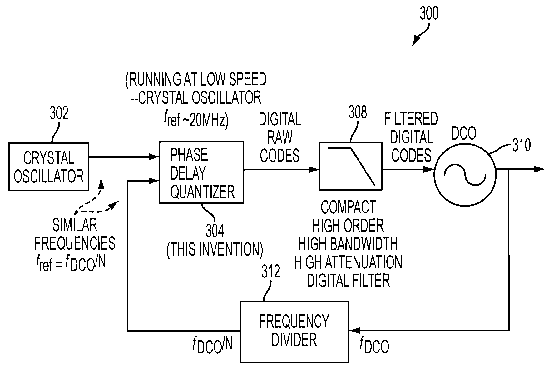
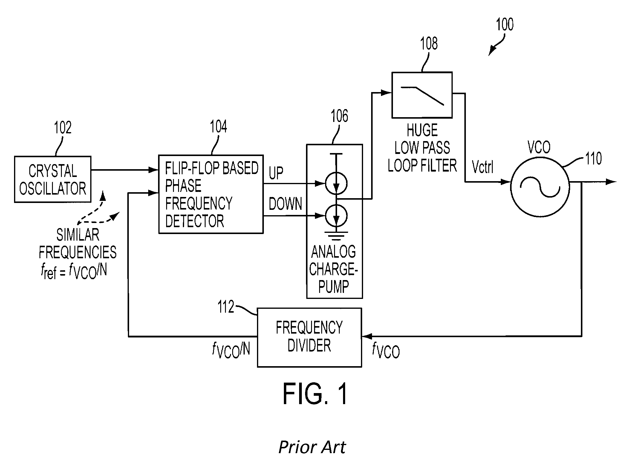
[0034]A phase locked loop circuit in accordance with an embodiment implements a digital phase delay quantizer to replace the analog charge-pump and phase frequency detector in PLL. Therefore, the built-in loop filter can be a compact-sized, high order, high bandwidth, and high attenuation digital filter as well. T...


PUM


Abstract

A phase locked loop circuit in accordance with an embodiment implements a digital phase delay quantizer to replace the analog charge-pump and phase frequency detector in an analog PLL circuit. Therefore, the built-in loop filter can be a compact-sized, high order, high bandwidth, and high attenuation digital filter as well. The digital PLL circuit takes advantage of the deep sub-micron process technology which features high speed, high resolution, compact size, and low power.

Description

FIELD OF THE INVENTION[0001]The present invention relates generally to phase locked loop circuits, and more particularly to an apparatus for providing phase delays for such circuits.BACKGROUND OF THE INVENTION[0002]Phase locked loop (PLL) circuits are used in a variety of applications. FIG. 1 is a diagram of a conventional analog PLL circuit 100. The VCO frequency fVCO is divided by a frequency divider 112 to get the divided VCO frequency fVCO / N. A flip-flop based phase frequency detector 104 compares a reference clock “fref”, obtains the divided VCO frequency “fVCO / N” and sends charge-up and charge-down signals to adjust the analog charge-pump 106. The charge-pump 106 adjusts the control voltage up or down based on the phase frequency detector 104 comparison results. The charge-pump 106 output voltage is low pass filtered by analog filter 108 and sent to the VCO 110 so as to tune the VCO frequency.Conventional Analog PLL Circuit Function[0003]In the conventional analog PLL circuit ...

Claims


Application Information

Patent Timeline
IPC IPC(8): H03L7/06H03L7/00
CPCH03L7/0802H03L2207/50H03L7/085
Inventor WU, I-CHANG
Owner MEDIATEK INC
Why Eureka
Try Eureka