In Situ Energy Harvesting Systems for Implanted Medical Devices

Inactive Publication Date: 2010-11-25
THE GOVERNMENT OF THE UNITED STATES OF AMERICA AS REPRESENTED BY THE DEPT OF VETERANS AFFAIRS
View PDF4 Cites 73 Cited by
  • Summary
  • Abstract
  • Description
  • Claims
  • Application Information

AI Technical Summary

Benefits of technology

[0016]The energy harvesting devices of the invention allow for the development of autonomous, integrated, self-powered implantable microsystems capable of providing for improved monitoring and treatment of conditions and diseases such as heart failure, high-level spinal cord injury, and aneurysms.
[0017]Thus, one aspect of the invention concerns patentable in situ biological energy harvesting devices. These devices harvest or recover a portion of the energy inherent in biological systems, such as living animals, including humans. In particular, they harvest mechanical and / or thermal energy present inside living organisms and convert it to electrical energy that can then be used for other desired purposes, for example, to power one or more implantable medical devices intended to monitor one or more physiological parameters inside a patient and / or to deliver a therapy, such as cardiac pacing, cardiac defibrillation, or drug (e.g., a hormone such as insulin, a chemotherapeutic agent, etc.). Such power sources can be used to produce self-powered implanted microsystems with continuous or near-continuous operation, increased lifetimes, reduced need for surgical replacement, and minimized or eliminated external interface requirements.

Problems solved by technology

The device is also located outside the arterial wall due, unlike intra-arterial devices that, by virtue of their placement, necessarily interact directly with blood (increasing the risk of complications) and may dislodge causing a stroke.
However, as the length increases, the PVDF begins to dominate the mechanical properties of the device and it restricts arterial expansion.
As can be seen in FIG. 6, this approximation is not exact and causes error in the theoretical model.

Method used


Image

  • In Situ Energy Harvesting Systems for Implanted Medical Devices
  • In Situ Energy Harvesting Systems for Implanted Medical Devices
  • In Situ Energy Harvesting Systems for Implanted Medical Devices

Examples


example 1

An Arterial Cuff Energy Harvester for Implanted Medical Microsystems

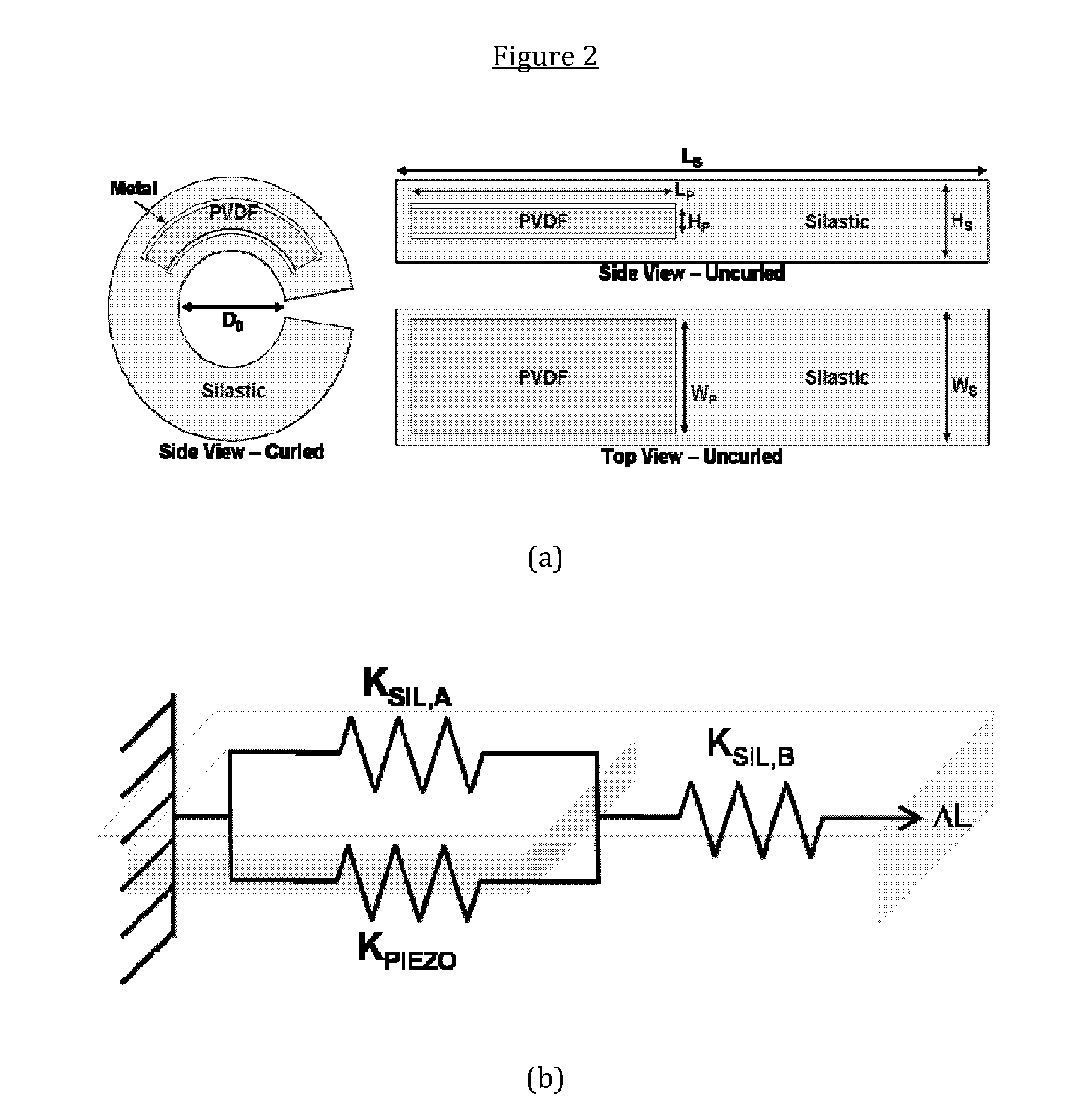
[0054]This example describes a miniature implantable power source that harvests (or scavenges) energy from the expansion and contraction of a mock artery. The energy harvesting element of the 0.25 cm3 device utilizes a piezoelectric thin film embedded within a flexible, self-curling medical-grade silicone cuff. Such an element can enable self-powered implanted microsystems with near-continuous operation, increased lifetime, reduced surgical replacement, and minimized or eliminated external interface requirements compared to conventional implanted medical devices. The fabricated device described in this example generates up to 16 nW when tested around a mock artery. Microfabricated versions of such an energy harvesting element should be capable of generating power outputs of greater than 1.0 μW.

I. INTRODUCTION

[0055]The example describes an arterial cuff energy scavenging (ACES) device that, for the first time, conver...

example 2

An Autonomous, Self-Powered Implanted Medical Microsystem

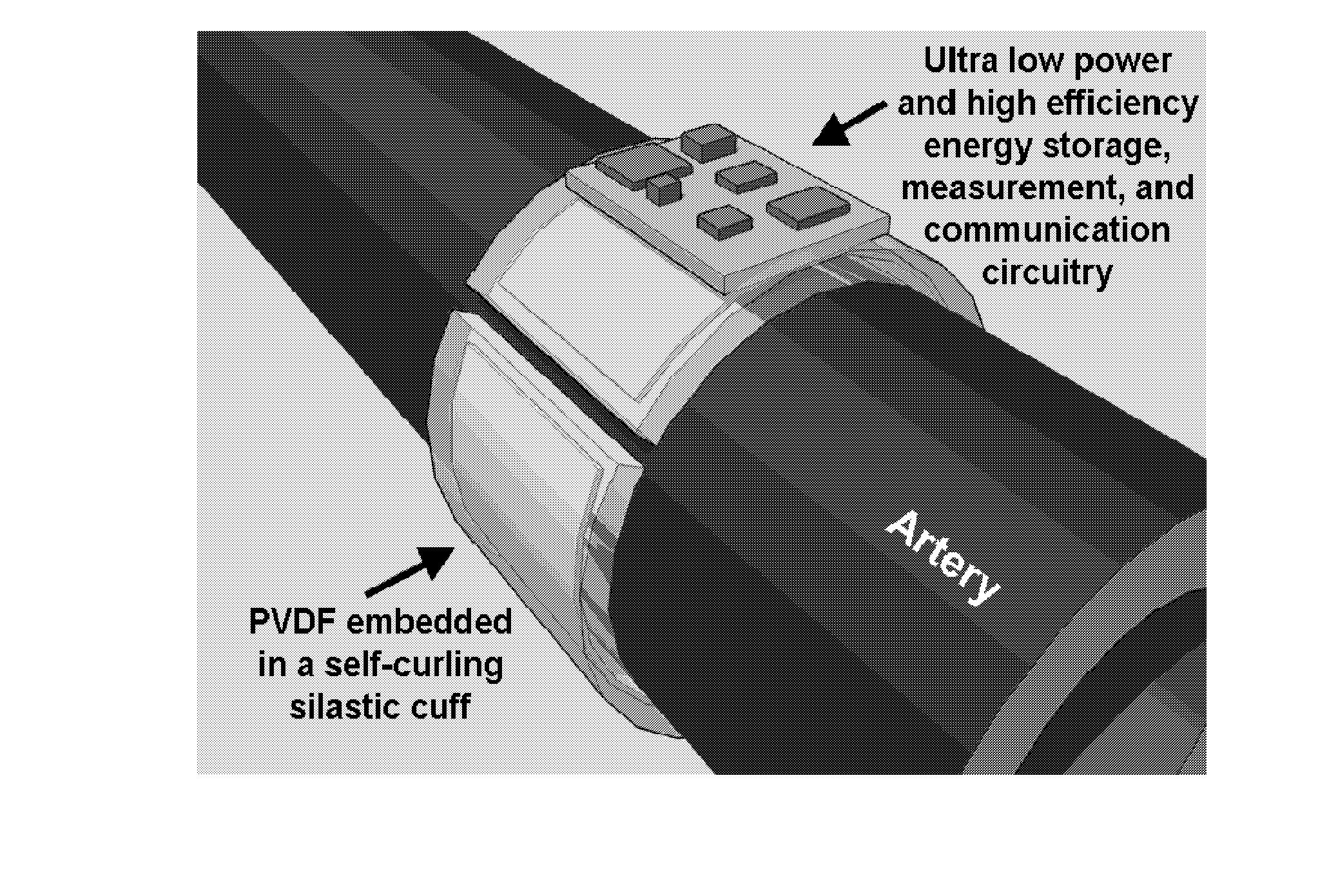
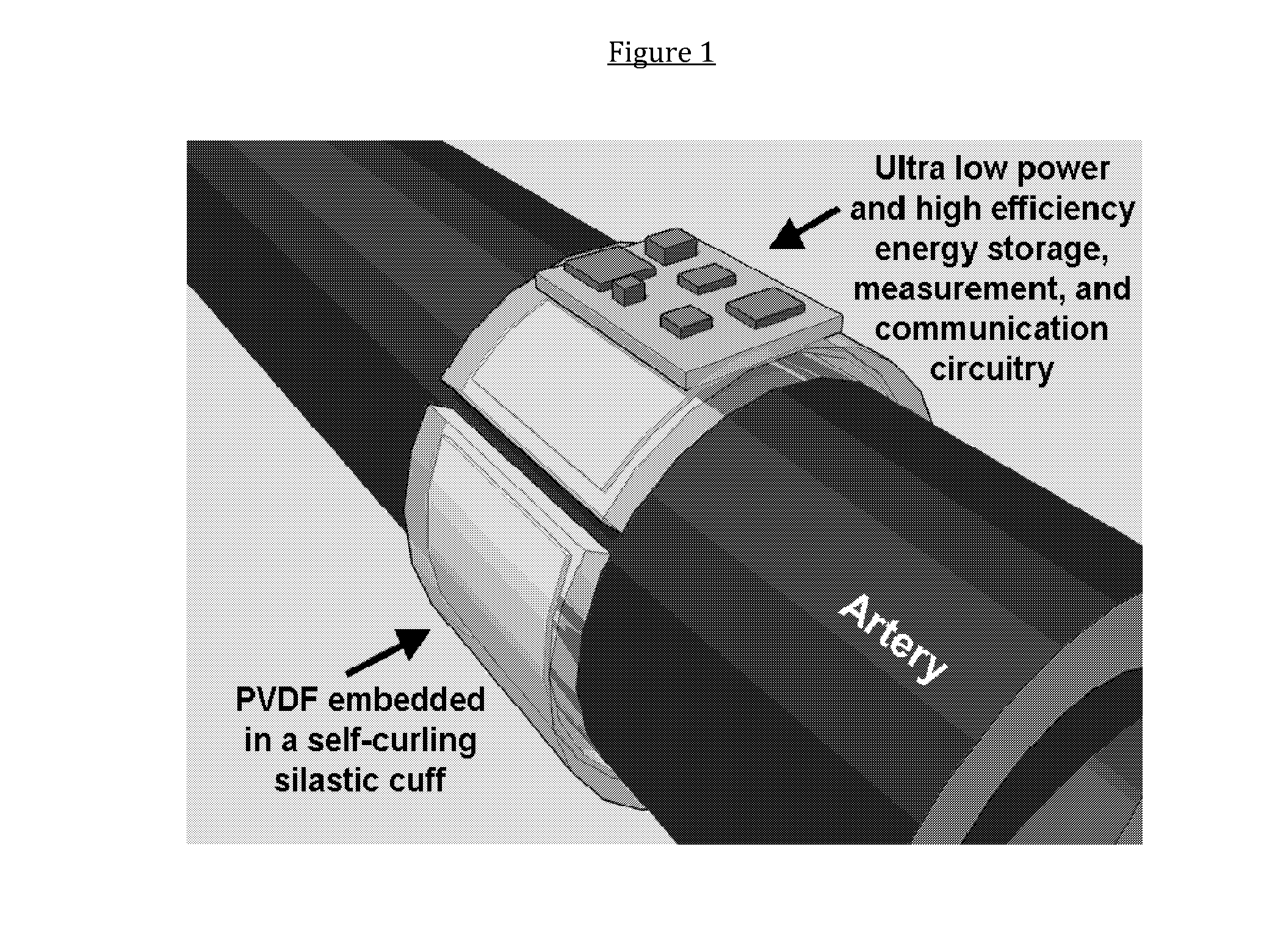
[0073]This example describes an autonomous implantable microsystem having an integrated energy harvesting device according to the invention. This microsystem device integrates an arterial cuff energy-harvesting device as described in Example 1, above, into a blood pressure sensing system with energy storage, measurement, and data storage circuitry (see FIG. 1). Blood pressure sensing is accomplished using a capacitive strain sensor utilizing a varying gap distance. The circuitry necessary to make the self-powered system will utilize low-turn-on-voltage diodes and low-leakage capacitors to rectify and store the electrical signal generated by the energy harvester. This stored energy will then be utilized by the device's blood pressure sensing system to periodically monitor blood pressure within the artery about which the implantable microsystem is deployed.

[0074]A block diagram of the complete the implantable microsystem is show...

example 3

Autonomous Implantable Microsystem Model

[0076]This example describes a representative circuit topology (see FIG. 8(a)) that can be used to simulate or test energy harvesting devices according to the invention. In this circuit the energy harvesting element (e.g., one comprised of a PVDF strip) is modeled as a voltage source in series with a capacitor. The energy storage circuitry utilizes a voltage doubler topology with two storage capacitors. The load is modeled as a resistor that is periodically switched on to draw power from the storage capacitors. As the artery expands and contracts, voltage generated by the PVDF film is rectified and charges up the load capacitors, CL1 and CL2. The results of a simulation of the circuit using values from the device described above in Example 1 are shown in FIG. 8(b). In this simulation, approximately 50 minutes was required between measurement cycles. The dips in the voltage represent two simulated measurement cycles that consume 2 μW of power f...


PUM


Abstract

This invention concerns miniature implantable power sources that harvest or scavenge energy from the expansion and contraction of biological tissues, for example, an artery or a bundle of muscle fiber. Such power sources employ an energy harvesting element that converts mechanical or thermal energy existing or generated in or from a pulsatile tissue into a form of electrical energy that can be used or stored by an implanted medical device, such as a blood pressure sensor, a flow meter, or the like. Preferred energy harvesting element embodiments utilize a piezoelectric thin film embedded within a flexible, self-curling medical-grade polymer or coating. Such power sources can be used to produce self-powered implanted microsystems with continuous or near-continuous operation, increased lifetimes, reduced need for surgical replacement, and minimized or eliminated external interface requirements.

Description

RELATED APPLICATIONS[0001]This patent application claims priority to and the benefit of U.S. provisional patent application Ser. Nos. 61 / 170,102 and 61 / 212, 999, filed on 16 and 17 Apr. 2009, respectively, the contents of each of which are hereby incorporated by reference in their entirety for any and all purposes.GOVERNMENT RIGHTS[0002]Research related to this invention was supported by Department of Veterans Affairs Rehabilitation Research and Development Grant C3819C, The Advanced Platform Technology Center of Excellence. The U.S. government may have certain rights in this invention.TECHNICAL FIELD[0003]This invention concerns devices and systems capable of harvesting energy in situ from biological systems in order to provide power for implanted medical devices.BACKGROUND OF THE INVENTION[0004]1. Introduction[0005]The following description includes information that may be useful in understanding the present invention. It is not an admission that any such information is prior art,...

Claims


Application Information

Patent Timeline
IPC IPC(8): A61N1/378A61B5/021A61B5/026A61B5/01
CPCA61B5/0215A61B5/076A61N1/3785A61B5/6876A61B2560/0214A61B5/6862
Inventor POTKAY, JOSEPH ALLEN
Owner THE GOVERNMENT OF THE UNITED STATES OF AMERICA AS REPRESENTED BY THE DEPT OF VETERANS AFFAIRS
Why Eureka
Try Eureka