Implantable medical device for cardiac electrical stimulation

a technology of electrical stimulation and medical devices, applied in the field of implantable medical devices, can solve problems such as triggering a tachyarrhythmia in the patient's heart that was susceptible, and achieve the effects of reducing the rate or blood pressure, reducing the ventricular rate, and reducing the systolic and diastolic blood pressur

Inactive Publication Date: 2010-11-25
MEDTRONIC INC
View PDF12 Cites 11 Cited by
  • Summary
  • Abstract
  • Description
  • Claims
  • Application Information

AI Technical Summary

Benefits of technology

[0008]Excitation of the atria, SAN and / or AVN during the ventricular refractory period resets the atrial cycle (resets the SAN) and starts a new refractory period in the atrial and AV nodal tissue, without triggering a ventricular contraction. The result is that propagation of a depolarization to the ventricles effective to cause a contraction is delayed until the next subsequent depolarization of the SAN. The ventricular rate is thus reduced by up to 50% from the SA nodal rate. The inventors have determined that in conjunction with this reduction in ventricular rate, both the systolic and diastolic blood pressures may be reduced. The degree of reduction in rate and blood pressure varies with the timing of the atrial or nodal excitation stimulus relative to preceding atrial and ventricular depolarizations. The effect of the stimulation can thus be titrated against a desired reduction in rate or blood pressure.

Problems solved by technology

However, it was realized that the application of closely timed paired and coupled pacing pulses, particularly the high energy pacing pulses that were employed at that time in implantable pacemakers, could trigger a tachyarrhythmia in patient's hearts that were susceptible.

Method used


Image

  • Implantable medical device for cardiac electrical stimulation
  • Implantable medical device for cardiac electrical stimulation
  • Implantable medical device for cardiac electrical stimulation

Examples


first embodiment

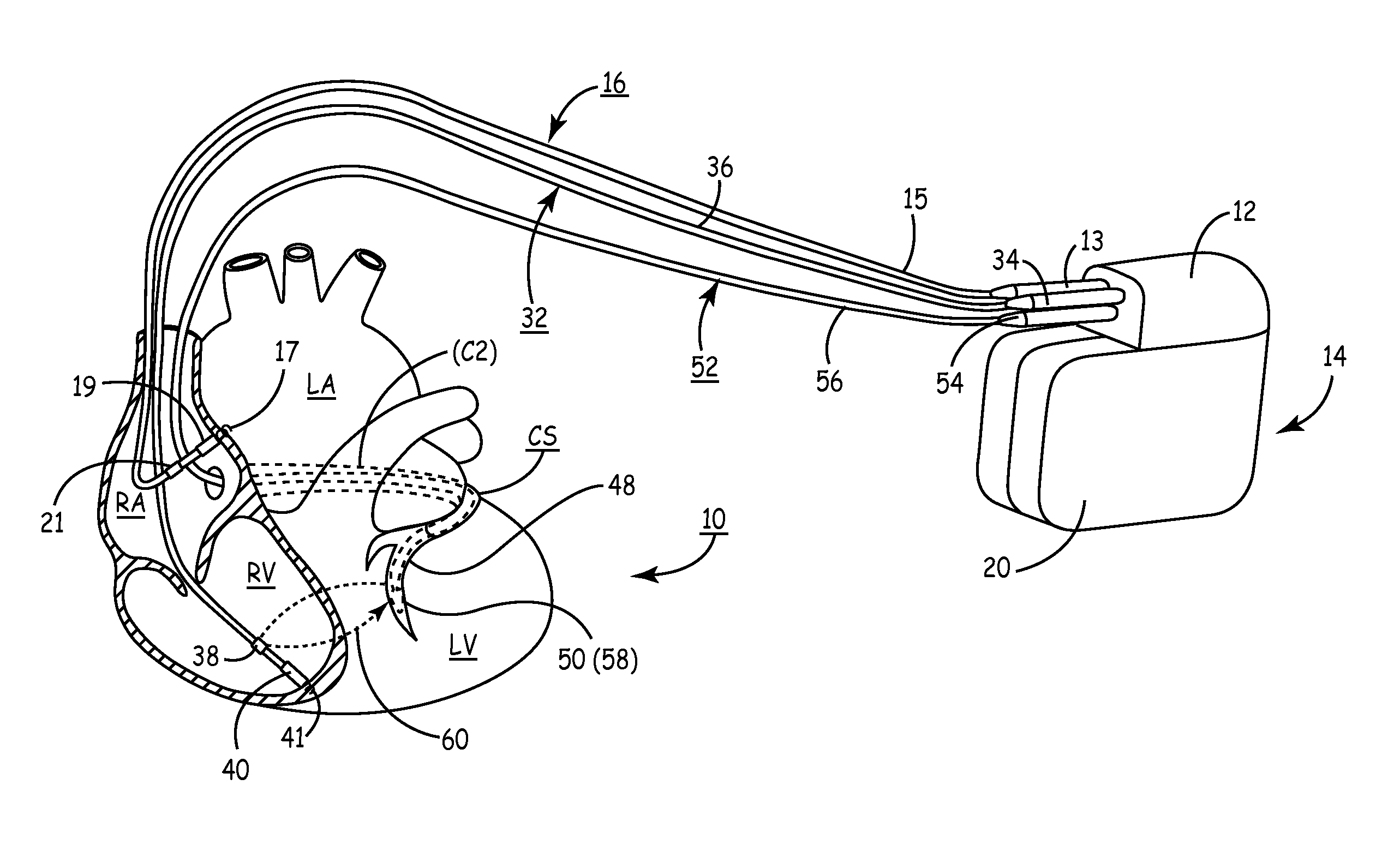
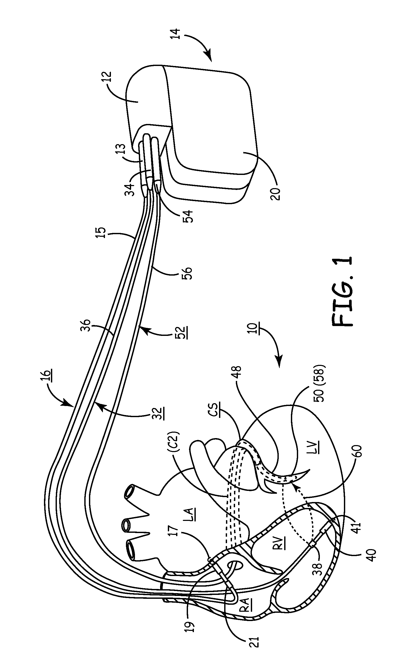
[0021]FIG. 1 depicts an implanted, multi-channel cardiac pacemaker according to the present invention for restoring AV synchronous contractions of the atrial and ventricular chambers and simultaneous or sequential pacing of the right and left ventricles. The pacemaker IPG 14 is implanted subcutaneously in a patient's body between the skin and the ribs. Three endocardial leads 16, 32 and 52 connect the IPG 14 with the RA, the RV and the LV, respectively. Each lead has at least one electrical conductor and pace / sense electrode, and a remote indifferent can electrode 20 is formed as part of the outer surface of the housing of the IPG 14. As described further below, the pace / sense electrodes and the remote indifferent can electrode 20 (IND_CAN electrode) can be selectively employed to provide a number of unipolar and bipolar pace / sense electrode combinations for pacing and sensing functions. The depicted positions in or about the right and left heart chambers are also merely exemplary. ...

second embodiment

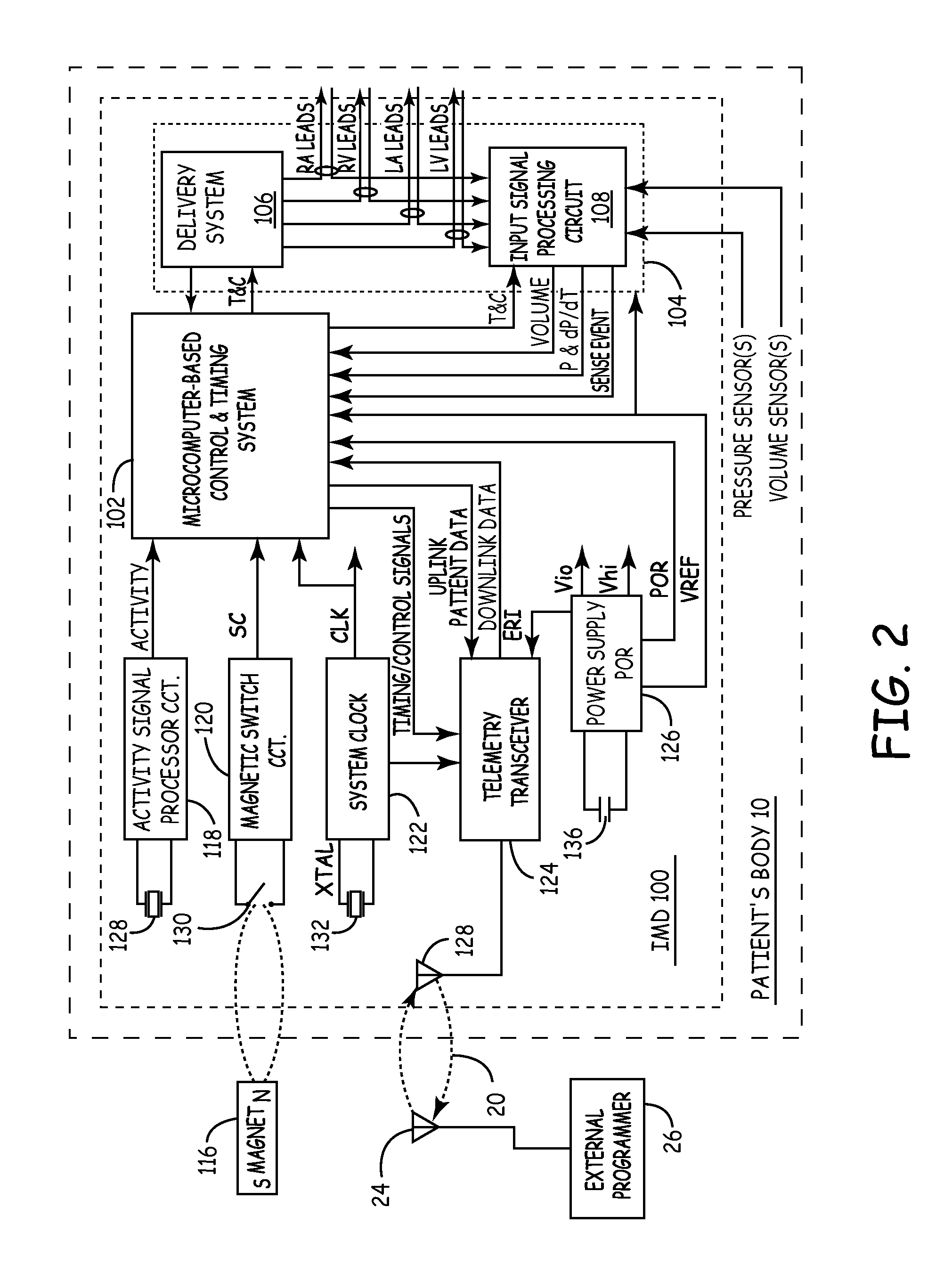
[0045]FIG. 4 is a functional flowchart illustrating the operation of a pacemaker practicing the present invention, in this case responsive to a sensed inappropriately high blood pressure. The operation of the pacemaker to provide the therapy is similarly controlled by the microprocessor responsive to software stored in memory, comprising instructions for causing the pacemaker to perform the described functions. The pacemaker checks at 402 to determine whether the blood pressure is elevated, e.g. by determining the pressure is above a defined threshold. Alternatively or additionally, the pacemaker may cross check the present pressure at 404 with a physiological sensor such as an activity sensor to determine whether the blood pressure is appropriate. If the blood pressure is determined to be excessive stimulation therapy according to the present invention is initiated at 406. The therapy is continued until either the blood pressure drops below a defined threshold at 408 (optionally al...


PUM


Abstract

A method and apparatus for reducing a patient's heart rate or blood pressure. The apparatus provides stimulation to the patient's atrial and / or nodal tissue within the associated refractory period of the ventricle but outside of an associated refractory period of the stimulated atrial an / or nodal tissue, responsive to detecting an occurrence of a ventricular depolarization following a preceding atrial depolarization.The apparatus may define a time window following the ventricular depolarization, following the atrial depolarization or determined based upon the timing of both the atrial and ventricular depolarizations. The stimulus may be delivered during or on expiration of the defined time window. The duration of the time window may be pre-set or determined based upon measurements of the patient's refractory periods.

Description

CROSS-REFERENCE TO RELATED APPLICATIONS[0001]This application claims the benefit of U.S. Provisional Application No. 61 / 179,452, filed on May 19, 2009. The disclosure of the above application is incorporated herein by reference.FIELD OF THE INVENTION[0002]The present invention relates generally to implantable medical devices and more specifically to cardiac stimulation.BACKGROUND OF THE INVENTION[0003]In the early days of implantable cardiac pacing, it was observed that paired pacing (two or more closely spaced pacing pulses delivered at the time-out of an escape interval) and triggered or coupled pacing (one or more pacing pulses delivered following the detection of a P-wave or R-wave terminating an escape interval) with relatively short inter-pulse intervals (150 to 250 milliseconds in dogs and about 300 milliseconds in human subjects) beneficially slowed heart rate and increased cardiac output. The result of the second pulse, applied within the relative refractory period of the f...

Claims


Application Information

Patent Timeline
Patent Type & Authority Applications(United States)
IPC IPC(8): A61N1/362A61N1/36A61B5/352
CPCA61B5/0215A61B5/024A61B5/02405A61N1/3702A61B5/0456A61N1/3621A61N1/3627A61B5/0452A61B5/352A61B5/349
Inventor SOMMER, JOHN LOUISBRABEC, SCOTT J.URBAN, JON FREDERICXIAO, YONG-FUZHOU, XIAOHONG
Owner MEDTRONIC INC
Why Eureka
Try Eureka