Absorbing wire grid polarizer
- Summary
- Abstract
- Description
- Claims
- Application Information
AI Technical Summary
Benefits of technology
Problems solved by technology
Method used
Image
Examples
embodiment 1
[0085]In a first embodiment of the invention, an absorbing wire grid polarizer is enabled by reducing the metal fraction. According to a simple model of the effective medium theory, the permittivity ε of a composite material consisting of parallel wires and dielectric for the direction of the electric field parallel to the wires is (Yeh, Opt. Comm. 26(3) 1978, 289-292):
εeff=fεm+(1−f)εd Equation 3
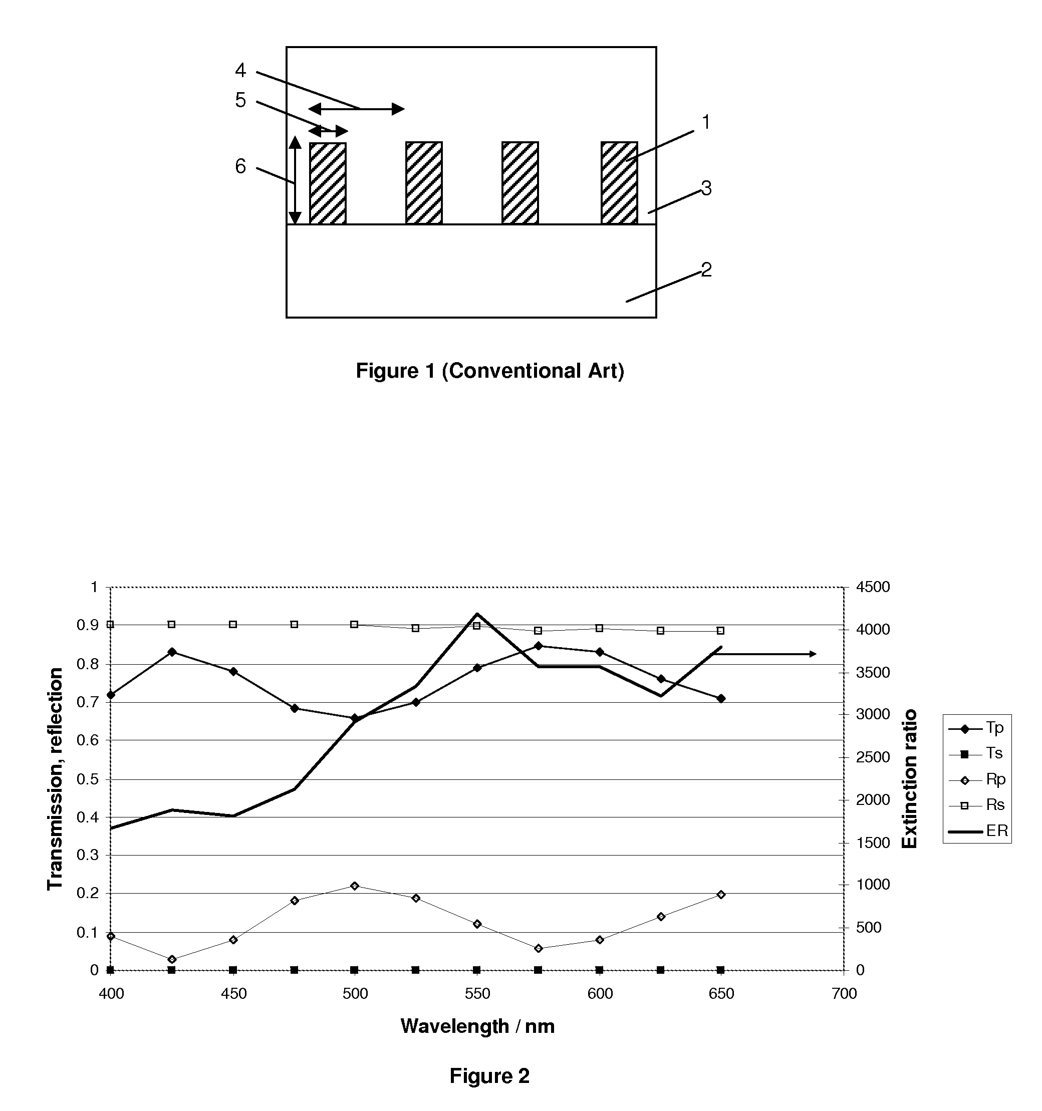
[0086]Here, εm and εd are the permittivities of the metal and the dielectric, respectively, with ε=n2 (for materials with permeability μ=1). FIG. 5a and 5b show schematically two example composite media with the high refractive index material 24, 25 of low volume fraction in the dielectric matrix 2. The high refractive index material 24, which can have a variety of cross sectional profiles such as rectangular with width 5 and height 6, or circular high refractive index material 25 with diameter 26, extends continuously over the length 23, forming thin wires of periodicity 4. The graph in F...
embodiment 2
[0088]In a second embodiment of the invention, an absorbing wire grid polarizer is proposed, which has wires made from a material that combines sufficiently low reflectance with absorbing properties in the visible wavelength range. Since the material forms nanometer-sized wire, the structural anisotropy enables selective absorption of the polarization direction parallel to the wires, whereas the polarization perpendicular to the wires is mostly transmitted.
[0089]An example material is graphite, which is shown to enable an absorbing polarizer in FIG. 7 and FIG. 8. Here, a periodicity of p=100 nm and two different wire width w and a wavelength of 550 nm were chosen as an example. The reflectivity for s-polarized light is about 9% (w / p=0.5) and 5%, (w / p=0.3) respectively, depending on the chosen geometry. The extinction ratio and transmission of p-polarization strongly depend on the wire thickness, and a compromise needs to be found between them. Reducing the duty cycle w / p improves th...
embodiment 3
[0093]This third embodiment is based on the absorbing wire grid polarizer in Embodiment 1, using low metal volume fractions to reduce the Rs surface reflections. Certain cross sections of the wires lead to a geometry where there is a low metal volume fraction on one side and a high metal volume fraction on the other side of the polarizer. For these geometries a double-sided polarizer is enabled that behaves differently when illuminated from one side or the other.
[0094]FIG. 10 shows an example of two wire profiles, a triangular 32 and a T-shaped one 37, which demonstrate absorbing / reflecting behavior. The schematic clarifies the geometry used for the simulation; the source location 29 remains static and the wire orientation is changed to point toward the source (solid outline of the structure) or away from the source (dashed outline of the structure). Transmission 31 and reflection 30 were simulated. FIG. 11 and FIG. 12 show the simulation results for the triangular profile wires 32 ...
PUM
| Property | Measurement | Unit |
|---|---|---|
| Fraction | aaaaa | aaaaa |
| Fraction | aaaaa | aaaaa |
| Dielectric polarization enthalpy | aaaaa | aaaaa |
Abstract
Description
Claims
Application Information
 - R&D
- Intellectual Property
- Life Sciences
- Materials
- Tech Scout
- Unparalleled Data Quality
- Higher Quality Content
- 60% Fewer Hallucinations
Browse by: Latest US Patents, China's latest patents, Technical Efficacy Thesaurus, Application Domain, Technology Topic, Popular Technical Reports.
© 2025 PatSnap. All rights reserved.Legal|Privacy policy|Modern Slavery Act Transparency Statement|Sitemap|About US| Contact US: help@patsnap.com


