
Controlling Top of the Line Corrosion in Hydrocarbon Pipelines

a technology for hydrocarbon pipelines and top of the line corrosion, which is applied in the direction of packaging, coatings, chemistry apparatuses and processes, etc., can solve the problems of high cost, high cost, and high risk of corrosion in the entire pipeline, and achieve the effect of cost-effectiveness

Inactive Publication Date: 2010-12-02
CONOCOPHILLIPS CO
View PDF6 Cites 10 Cited by
  • Summary
  • Abstract
  • Description
  • Claims
  • Application Information

AI Technical Summary

Benefits of technology

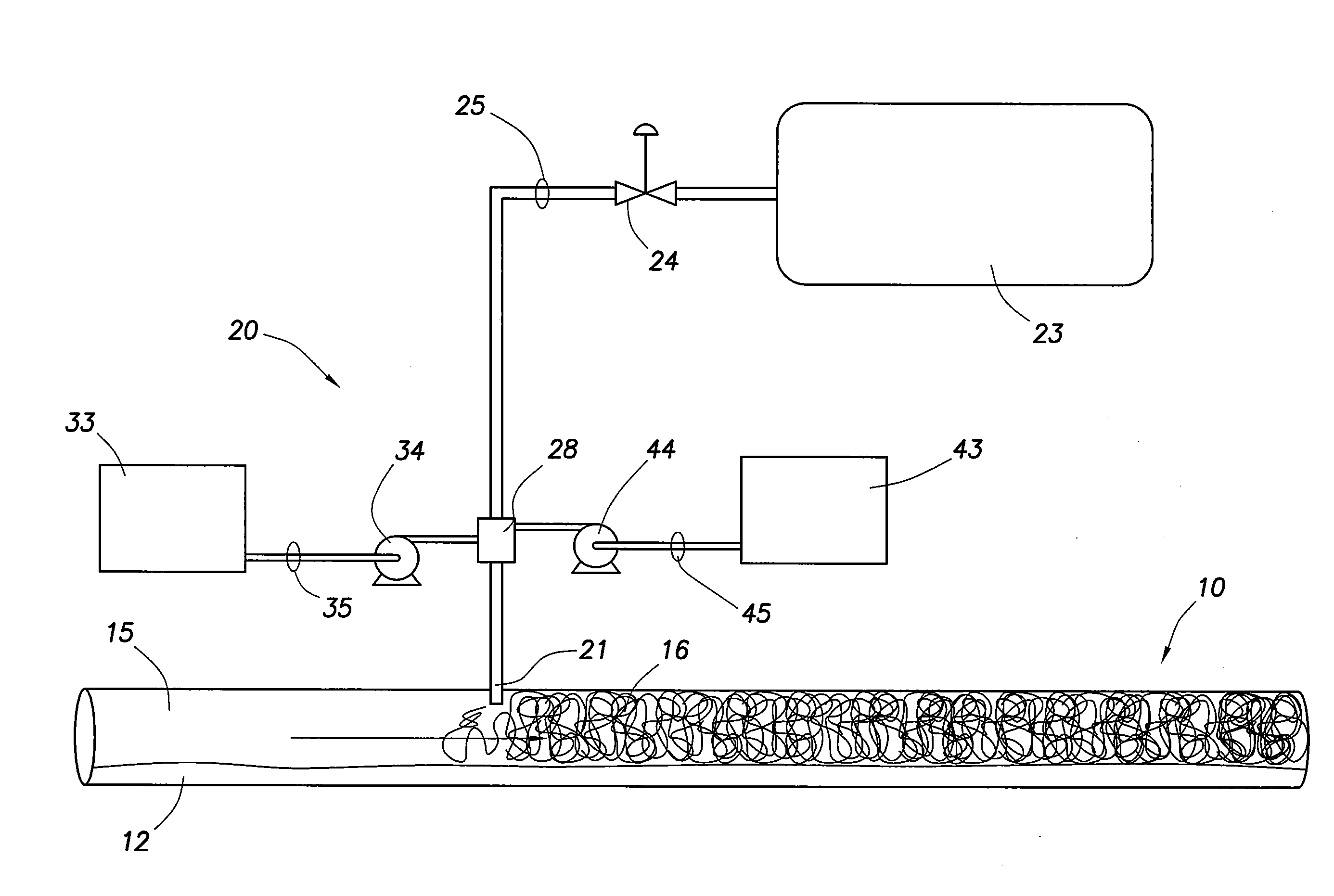
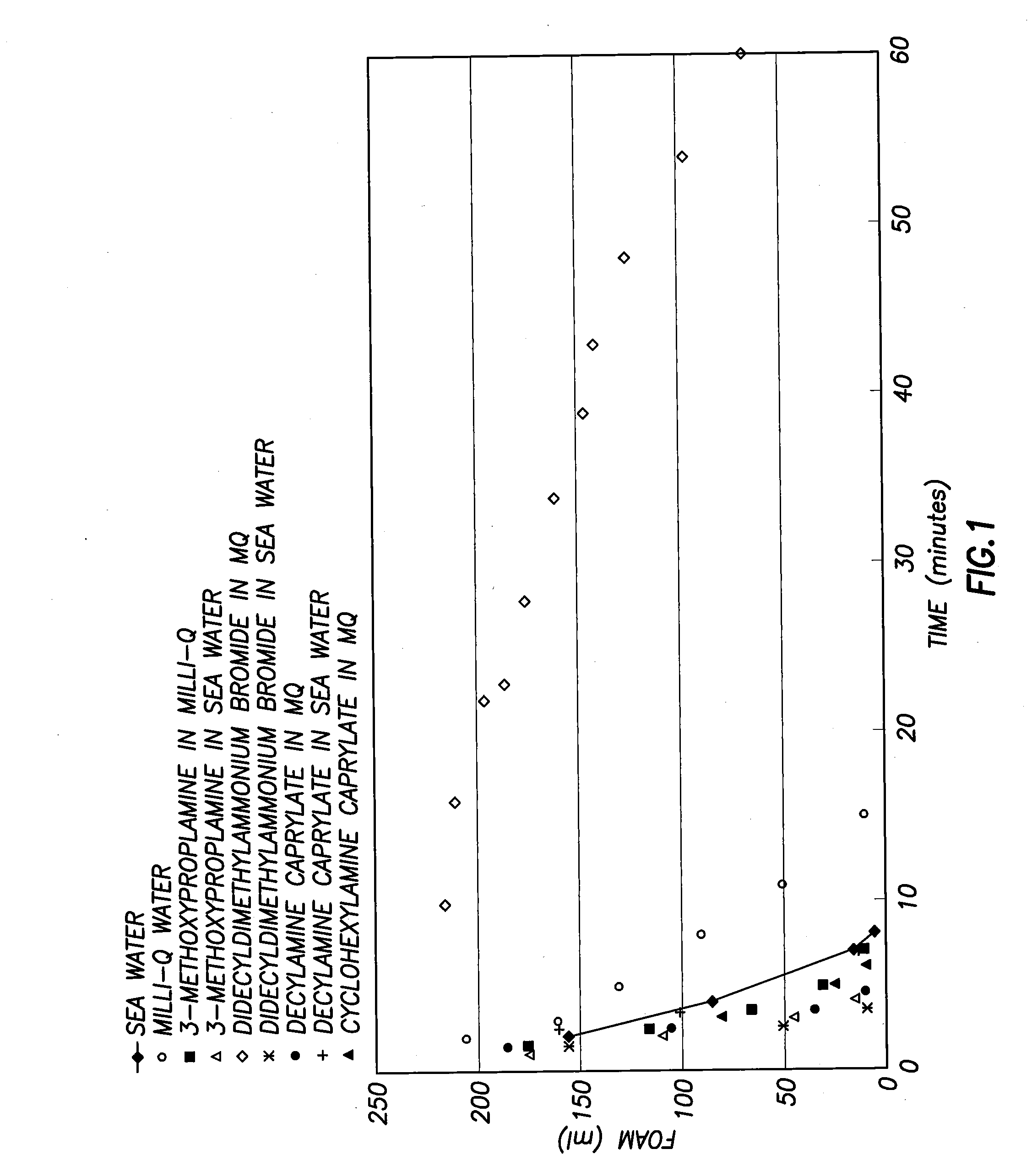
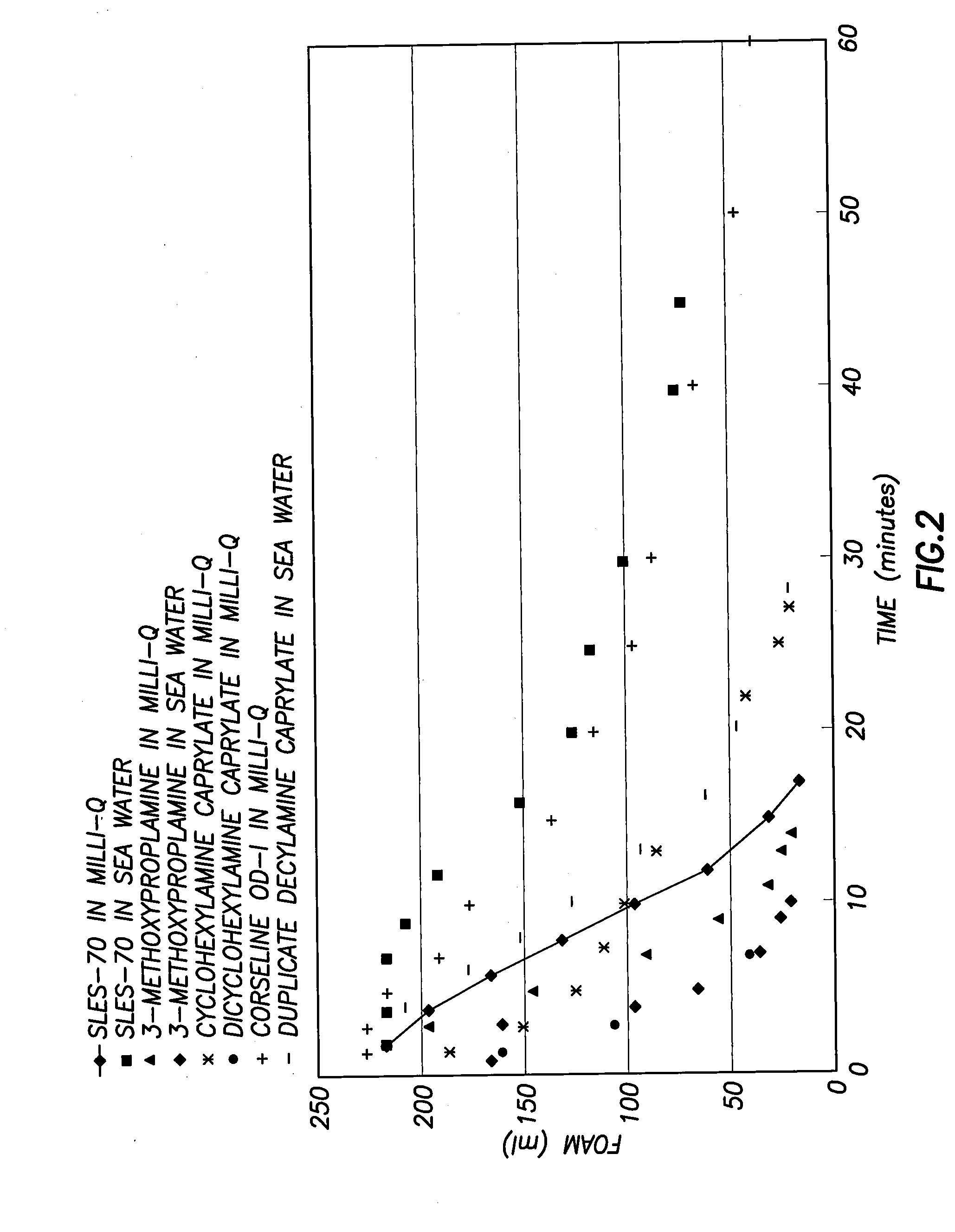
[0011]In another aspect the present invention relates to a process for applying a corrosion inhibiting solution to a pipeline carrying a live hydrocarbon solution where the corrosion inhibiting solution includes a foaming gas, a foaming agent, a corrosion inhibitor and a foam breaking agent where foam is formed in the pipeline that carries a concentration of corrosion inhibitor to the top of the line twelve o′clock position inside the pipeline while the pipeline is carrying the hydrocarbons and without interruption. The process for applying the solution generally includes a first step of analyzing hydrocarbons that are to be flowing in the pipeline and creating a test hydrocarbon solution for testing foaming agents, corrosion inhibitors and foam breaking agents. A number of foaming agents are tested with the test hydrocarbon solution to identify foaming agents that are effective at creating foam, and then the foaming agents that are effective in the test hydrocarbon solution are tested with a number of corrosion inhibitors in the test hydrocarbon solution to identify combinations of foaming agent and corrosion inhibitors that are most effective at maintaining adequate concentrations of corrosion inhibitor in the foam and sufficient foam quantity to apply foam to the twelve o′clock position in the pipeline for the full length of the pipeline. A number of foam breaking agents are tested to verify that the foam formed by the effective foaming agent in combination with the effective corrosion inhibitors in combination with the test hydrocarbon solution will be effectively stifled by one or more foam breaking agents. The process further includes identifying at least one cost effective combination of foaming agent, corrosion inhibitor, and foam breaking agent with the test hydrocarbon solution and testing the combination(s) of foaming agent, corrosion inhibitor, and foam breaking agent with live hydrocarbon solution in the pipeline and adjusting the injection rate of the foaming gas, the foaming agent and the corrosion inhibitor so that a concentration of corrosion inhibitor is applied to the top of the line twelve o′clock position along the length of the pipeline, and adequate foam breaking agent is provided at the end of the pipeline to prevent foaming of the hydrocarbon during subsequent processing thereof.

Problems solved by technology

Hydrocarbon pipelines constructed from carbon steel are vulnerable to corrosion, especially corrosion caused by organic acids and acid compounds of H2S and CO2 dissolved in water.
However, the entire pipeline, including the very top of the line at the twelve o′clock position, is vulnerable to corrosion since the corrosion inhibitors tend to stay with the liquid at the bottom of the line.
Any pipeline with stratified flow is particularly vulnerable to corrosion as the corrosion inhibitors typically remain concentrated in the liquid solution at the lower portion of the pipeline.
Unfortunately, batch inhibition using pigging can be expensive and many pipelines are designed or constructed in a manner that cannot be pigged.
To the extent that a pipeline may have been designed to be amenable to pigging, a pig disrupts production through the pipeline, especially as it first enters the pipeline.
A potential interruption of the gas flow would create considerable costs as the plant is shut and restarted.
However, gelatin materials are not suitable for warmer pipelines and do not necessarily assume the full diameter of the pipeline after a passing through a substantially smaller diameter valve or other restriction.
However, such corrosion resistant alloys are far more expensive than common carbon steel and are typically used in areas where it is impractical to apply corrosion inhibition.

Method used


Image

  • Controlling Top of the Line Corrosion in Hydrocarbon Pipelines
  • Controlling Top of the Line Corrosion in Hydrocarbon Pipelines
  • Controlling Top of the Line Corrosion in Hydrocarbon Pipelines

Examples


Embodiment Construction

[0017]Turning now to the preferred arrangement for the present invention, reference is made to the drawings to enable a more clear understanding of the invention. However, it is to be understood that the inventive features and concept may be manifested in other arrangements and that the scope of the invention is not limited to the embodiments described or illustrated. The scope of the invention is intended only to be limited by the scope of the claims that follow.

[0018]This invention is focused on reducing corrosion in hydrocarbon pipelines and especially at the top or twelve o′clock position with long pipelines. For example, in a natural gas well, other gases are produced along with methane, ethane, propane, butane, pentane, hexane and other hydrocarbons. Such other gases include water vapor, carbon dioxide and hydrogen sulfide and other known organic materials and impurities. As the natural gas is produced, it starts at the temperature of the formation from which it was produced. ...


PUM

PropertyMeasurementUnit
Lengthaaaaaaaaaa
Concentrationaaaaaaaaaa
Corrosion propertiesaaaaaaaaaa

Abstract

The invention relates to applying corrosion inhibitor within a foam matrix to the top of the line of wet gas pipelines. The environment within a hydrocarbon containing pipeline may include fluids that form strong acids in the gas space at the upper portion of the pipeline and can rapidly corrode a carbon steel pipeline. The inventive solution is to provide a foam matrix created by a combination of foaming agent, foaming gas and corrosion inhibitor that are each selected to be compatible with each other and with the hydrocarbon mixture to form a stable foam matrix that treats the top of the line position for the length of the pipeline. A foam breaking agent at the end of the pipeline can be injected, if needed.

Description

CROSS-REFERENCE TO RELATED APPLICATIONS[0001]This application is a non-provisional application which claims benefit under 35 U.S.C. §119(e) to U.S. Provisional Application Ser. No. 61 / 183,381 filed Jun. 2, 2009, entitled “Controlling Top of the Line Corrosion in Hydrocarbon Pipelines,” which is incorporated herein in its entirety.STATEMENT REGARDING FEDERALLY SPONSORED RESEARCH OR DEVELOPMENT[0002]None.FIELD OF THE INVENTION[0003]This invention relates to the application of anticorrosion materials to the inside of hydrocarbon pipelines.BACKGROUND OF THE INVENTION[0004]Hydrocarbon pipelines constructed from carbon steel are vulnerable to corrosion, especially corrosion caused by organic acids and acid compounds of H2S and CO2 dissolved in water. To prevent or avoid material loss from corrosion, it is common to inject corrosion inhibitors into the pipeline. However, the entire pipeline, including the very top of the line at the twelve o′clock position, is vulnerable to corrosion since...

Claims


Application Information

Patent Timeline
IPC IPC(8): B05D1/00C23C16/52
CPCB05D7/222C09K8/54C23F11/02C23F11/14B05D7/22
Inventor ACHOUR, MOHSEN H.BLUMER, DAVID J.BAUGH, THOMAS D.
Owner CONOCOPHILLIPS CO
Learn More