[0015]Therefore, it is the object of the invention to further develop a method and an optical arrangement of the type described in the beginning in such a way that the
impact of these effects in the spatial representation of the specimen can be mitigated.
[0017]Accordingly, the method according to the invention is essentially a matter of combining the two methods of SPIM and OPT carried out on the same specimen. Since the specimen must be rotated in both cases to obtain a more or less
complete data set, substantially the same setups can be used, wherein the illumination adjustments and / or imaging adjustments are adapted to the respective selected methods. Based on the data obtained with OPT, it is possible to identify artifacts in the SPIM image, i.e., the first
data set, more easily. This reduces susceptibility to erroneous interpretations.
[0019]With the method that has just been described, artifacts can be detected in the SPIM image, but not eliminated. However, it is possible to do so when the first data set and second data set are fused to form a common data set of
spatial image data by means of a registration
algorithm. The first data set and second data set are accordingly transformed into a common coordinate
system and, in this way, can be superimposed in the representation in a spatial image. It is also possible, for example, to use the data of the OPT recordings to eliminate the artifacts in the image of the SPIM recording having a higher resolution by computational means. In so doing, the fact that both methods can work with different illumination wavelengths can be made use of For example, the
fluorescence of dyes contained in the specimen can be excited by SPIM illumination, but the OPT illumination can also lie in the
infrared wavelength region. The choice of this
wavelength region offers the
advantage that the light can penetrate more easily into the specimen and there is less scatter loss. The second data set obtained in this way can then be used as a unified marker channel for SPIM
fluorescence measurement. Of course, the specimen can also be illuminated with light which excites
fluorescence in the OPT method, for example, with light of the same
wavelength as in the SPIM method. The same
light source can then be used. Although the bleaching out of the specimen is more pronounced in this case and scatter losses can also be higher, the second data set can nevertheless be used to reconstruct a complete image of the specimen because the second data set has a higher integrity in
spite of
low resolution.
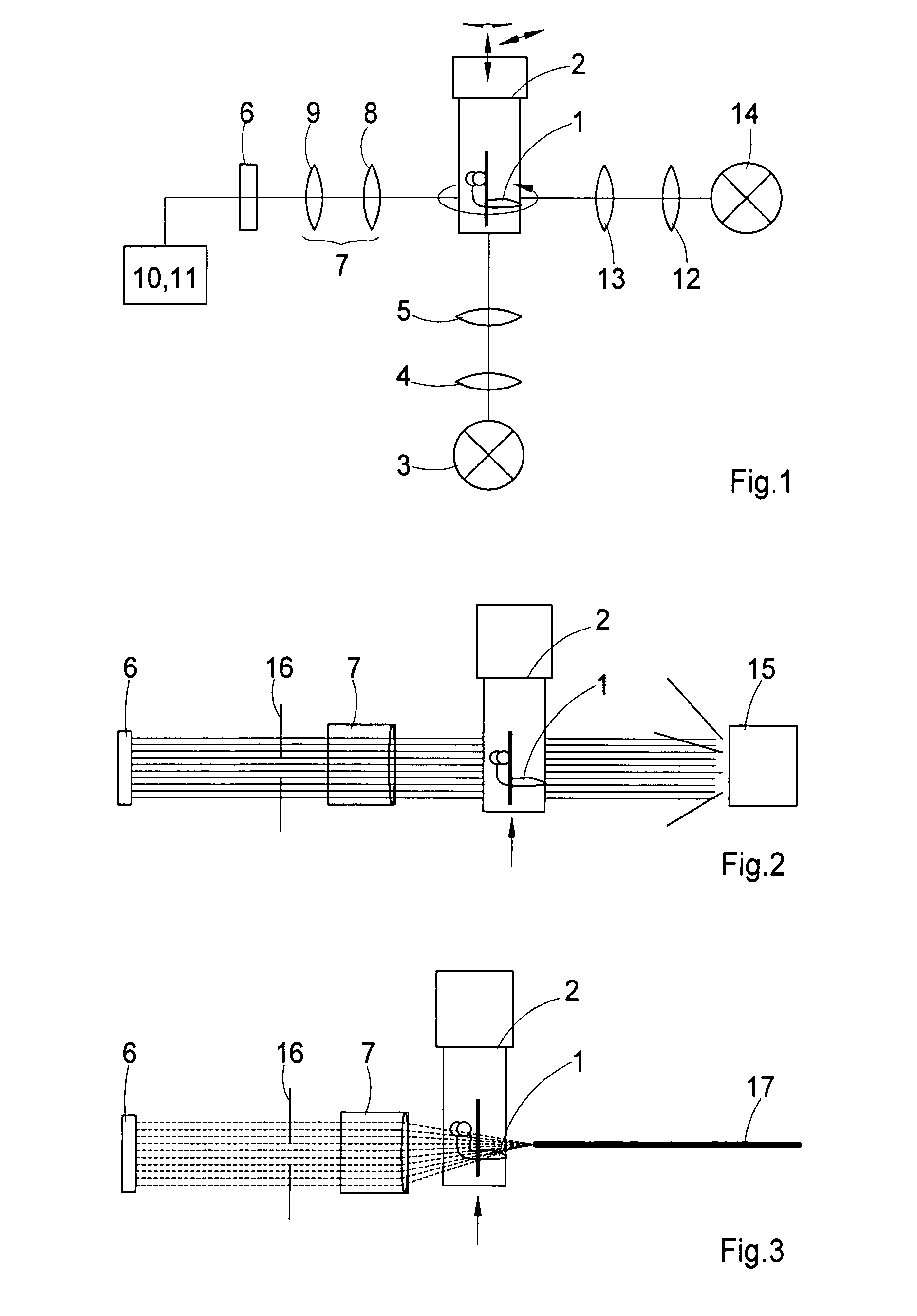
[0021]However, the second illumination device can also illuminate confocally with a
point light source, in which case the light of the
point light source preferably scans the specimen point by point. Because of the projection, light is registered only in the pixel, e.g., of a
CCD camera which corresponds—parallel to the
optical axis—to the actual position of the light point. In this way, effects occurring as a result of scattering can be entirely or at least almost entirely eliminated.
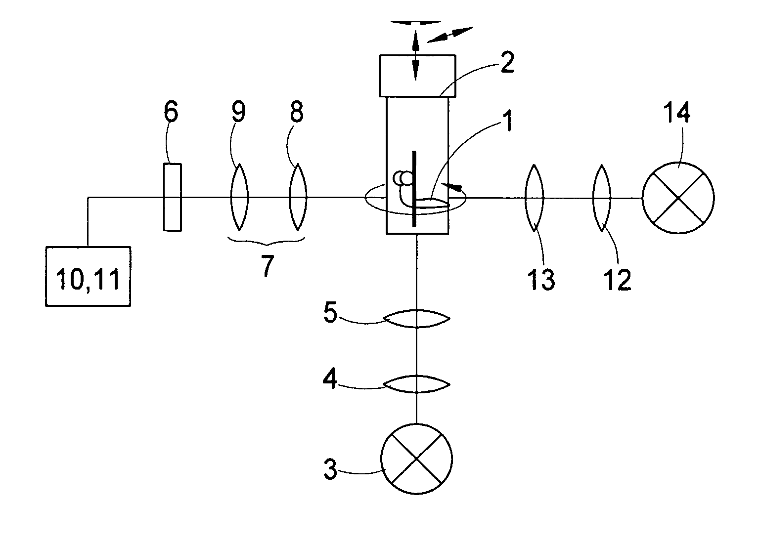
[0027]The imaging
optics preferably have, in a
pupil plane, means for adjusting the
depth of focus, preferably comprising a diaphragm wheel or an iris stop. This is particularly advantageous when using imaging systems with a
high numerical aperture which have a shallow
depth of focus. SPIM systems also generally work with low numerical apertures on the order of 0.2; but in OPT systems it is more advantageous to work with numerical apertures of less than 0.1 because the
depth of focus is increased in this way. It is also possible in principle to use lens systems with a
high numerical aperture, particularly also in the SPIM
system. However, so as to avoid changing the objective when switching from a SPIM measurement to an OPT measurement—which is, of course, possible when the objectives are arranged, for example, on a
turret—a diaphragm wheel or an iris stop can be used and correspondingly controlled, for example, when changing from SPIM illumination to OPT illumination, and vice versa, to adapt the imaging
optics to the respective
observation method.
[0028]Further, in a particularly preferred construction of the invention, a registration
algorithm is implemented in the evaluating unit, and the first data set and second data set can be fused to form a common data set of spatial image data by means of this registration algorithm. In this way, it is possible not only to detect artifacts in SPIM images, for example, but also to correct them in a corresponding manner. Of course, a simple superimposed representation of both image data sets is also possible when they are transformed into the same coordinate
system.

