Molding with embedded coupling particles for biomolecules

Inactive Publication Date: 2010-12-16
FRAUNHOFER GESELLSCHAFT ZUR FOERDERUNG DER ANGEWANDTEN FORSCHUNG EV
View PDF6 Cites 3 Cited by
  • Summary
  • Abstract
  • Description
  • Claims
  • Application Information

AI Technical Summary

Benefits of technology

[0049]A further advantage of the invention can be seen as being that, through the filler loading and the particle size, specific coupling densities of biomolecules on the inventive moldings can be set. On top of this it is possible, through the use of different coupling particles, thus coupling particles which have differing coupling chemistries, to specifically bind more than one species (or type of species) of biomolecules. Since the concentration of the various coupling particles can also be set separately in each case, it is thus also possible also to control the concentration of the loading of the surface of the inventive molding with specific biomolecules independently of one another, where the biomolecules have a different binding chemistry.
[0050]Furthermore, it is in particular possible for matrix materials in polymer synthetic materials, to considerably improve the ratio of specific to non-specific bindings: even if for the matrix material a synthetic material is selected which is not completely inert in relation to the biomolecules to be bound (or other biomolecules, to which the molding is exposed), through the specifically selected binding chemistry of the coupling particles a particularly high affinity to the desired biomolecules can be set, so that in areas in which the coupling particles are exposed through the mechanical treatment, a substantial enrichment of the biomolecules takes place.
[0051]For the manufacture of the molding a person skilled in the art will match the desired manufacturing method, the matrix material and the coupling particles, here in particular their size and/or form, to one another. There is extensive experience on this, e.g. in the area of injection molding.
[005

Problems solved by technology

This form of binding is often of limited stability and binding energy.
In addition the binding, because it is unaligned, often takes place in such a way that considerable proport

Method used


Image

  • Molding with embedded coupling particles for biomolecules
  • Molding with embedded coupling particles for biomolecules
  • Molding with embedded coupling particles for biomolecules

Examples


Example

Example 1

Manufacture of Moldings

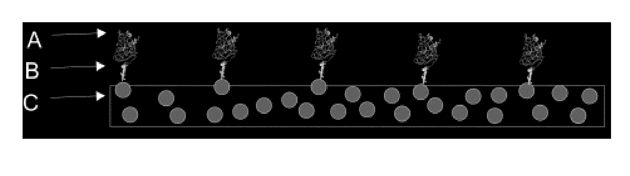
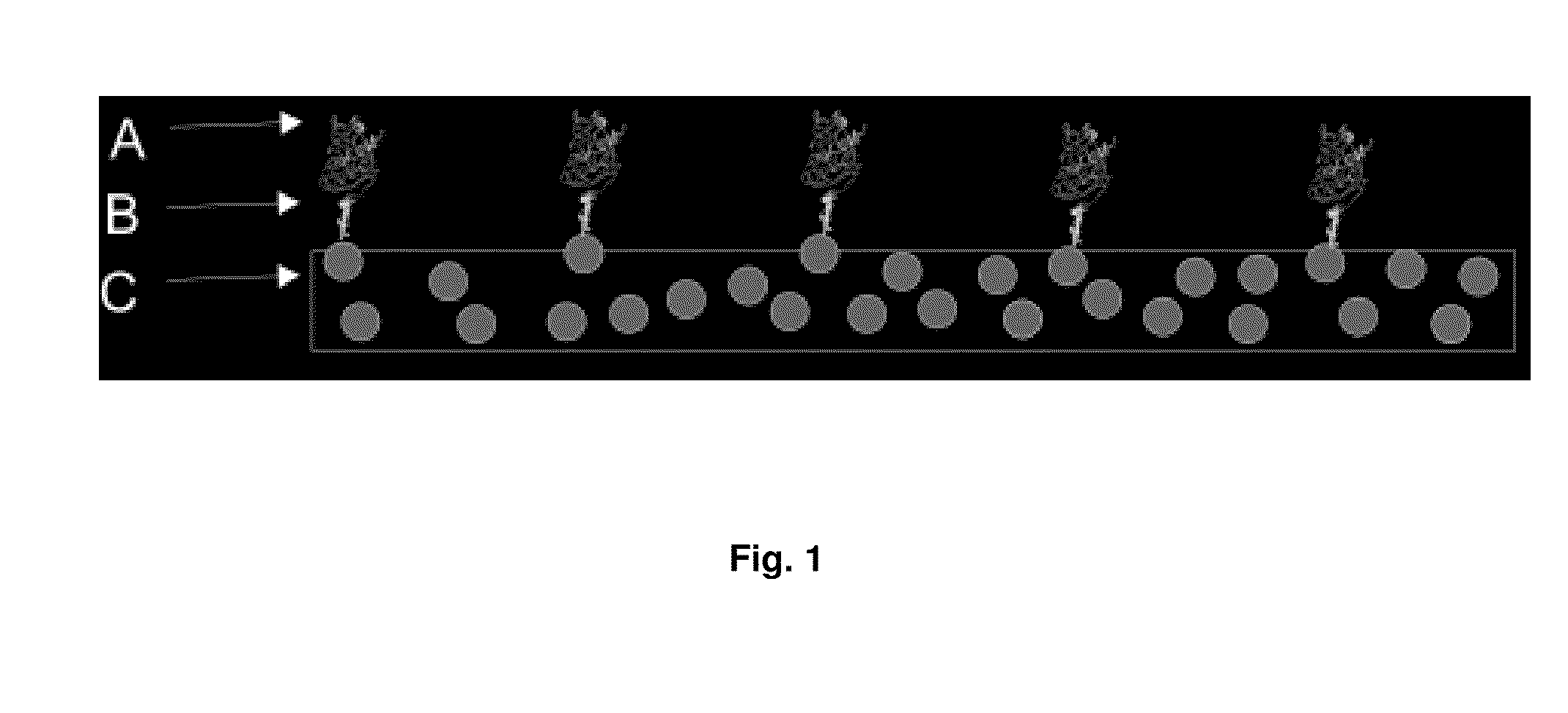
[0096]For the coupling of biomolecules to solid centers (coupling particles) in the first step a composite is manufactured from the respective solid in powder form and a thermoplastic polymer. Manufacture takes place in a temperature-controlled mixer, which heats the thermoplastics to above the heat distortion temperature and plasticizes them through mechanical working. For the manufacture of the composites used a Brabender Plastograph was employed.

[0097]For the dispersion the thermoplastic was placed in the pre-heated mixer and plasticized through mechanical shearing forces. Then the coupling particles were added dry as an ultrafine powder. After a mixing time of approximately 60 minutes the material was cooled slowly. The result was a granulate.

[0098]For the manufacture of the material composite, various material combinations were considered. For the base synthetic material, polypropylene (PP), polystyrene (PS), polyethylene (PE) and polyurethane (P...

Example

Example 2

Moldings

[0104]As a further geometry, in the injection molding method, spherical-cylindrical moldings were manufactured. Table 4 gives an overview of the material combinations produced:

TABLE 4Material combination for spherical-cylindrical moldingsContent ofDwellcouplingpressureparticlesMixingMixerInjectionAirfor 30SyntheticCoupling[% bytemperaturetimemoldingpressuresecondmaterialparticlevolume][° C.][min]temperature[bar]settingPEXX1251512540.5PEXXXX12540.5PEGlass1012515128-13040.5(S38)PENickel1012515128-13040.5(Novamet)

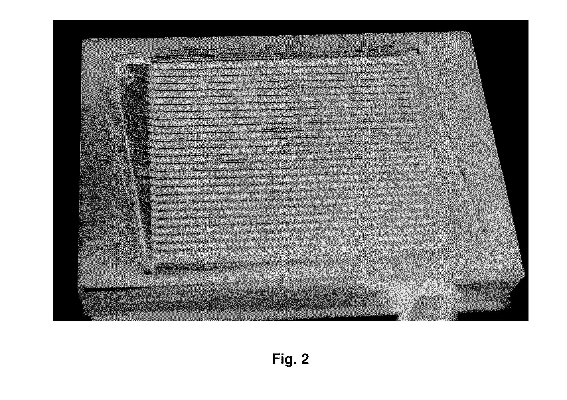
[0105]FIG. 3 shows injection molded parts (moldings) with 10% by volume of glass balls (average particle diameter of 20 μm) in a polyethylene matrix.

[0106]For the biochemical reaction (coupling) the active centers (glass balls) must now be exposed. This can take place by means of various methods, such as for example chemical or plasma-chemical etching. With these methods, however, often new unselective active centers in the form of carboxyl or similar groups a...

Example

Application Example 3

Coupling to Nickel Coupling Particles

[0115]Moldings manufactured according to Example 1 of the photoreactor type in polyethylene (Lupolen) as the matrix material and 5% by weight nickel particles with an average particle diameter of 2.3 μm (Fritsch) as coupling particles were exposed to a solution of the protein TNFalpha, provided with a histidine tag. The matrix material used without nickel particles served as a control. Mechanical removal by grinding was applied in each case to the moldings. The moldings with and without nickel particles were incubated with a TNFalpha solution of 10 mg / ml in phosphate buffered saline solution (PBS) for 3 hours at ambient temperature on a tilting shaker. Then excess or unbound protein was treated with a washing solution (PBS with 0.1% [v / v] of the detergent Tween 100). The bound protein TNFalpha was then detected by an antibody-mediated enzyme test, as this is carried out in the Enzyme-Linked Immunoabsorbent Sandwich Essay (ELI...


PUM

PropertyMeasurementUnit
Fractionaaaaaaaaaa
Fractionaaaaaaaaaa
Fractionaaaaaaaaaa

Abstract

The invention relates to a molding, comprising a matrix in a material, selected from the group consisting of metal, ceramic and polymer synthetic material, and coupling particles embedded in the matrix, wherein a proportion of the surface of the molding in a geometrical form or in a regular pattern and/or an area of the molding is completely or the entire surface of the molding is mechanically treated.

Description

CROSS REFERENCE TO RELATED APPLICATIONS[0001]Not ApplicableSTATEMENT REGARDING FEDERALLY SPONSORED RESEARCH OR DEVELOPMENT[0002]Not ApplicableFIELD OF THE INVENTION[0003]The invention relates to a molding, comprising a matrix in a material, selected from the group consisting of metal, ceramic and polymer synthetic material and coupling particles embedded in the matrix, wherein a proportion of the surface of the molding in geometrical form or in a regular pattern and / or an area of the molding is completely or the entire surface of the molding is mechanically treated.[0004]In particular the invention relates to a molding, comprising a polymer synthetic material matrix and coupling particles embedded therein, wherein the molding is mechanically treated, so that a proportion of the particle is at least not covered by the synthetic material matrix or the surrounding metal or ceramic matrix, and wherein a proportion of the surface of the molding in a geometrical form or in a regular patte...

Claims


Application Information

Patent Timeline
IPC IPC(8): B32B3/10B29C45/14G01N33/53C12P1/00C12M3/00C11D17/00
CPCB29C70/64C12N11/00G01N33/543G01N33/54313Y10T428/24405
Inventor SALK, NATALIEGRUNWALD, INGO
Owner FRAUNHOFER GESELLSCHAFT ZUR FOERDERUNG DER ANGEWANDTEN FORSCHUNG EV
Why Eureka
Try Eureka