High throughput development method for catalytic hydroprocessing of dirty feedstocks

a technology of catalytic hydroprocessing and high throughput, which is applied in the direction of sequential/parallele process reactions, laboratory equipment, chemistry apparatus and processes, etc., can solve the problems of low reaction rate, selectivity loss, and insufficient and quantitatively addressed open hds literature, and achieve high productivity and selectivity , the effect of low cos

Inactive Publication Date: 2010-12-23
ACCELERGY CORP
View PDF16 Cites 12 Cited by
  • Summary
  • Abstract
  • Description
  • Claims
  • Application Information

AI Technical Summary

Benefits of technology

[0014]This invention relates to a low cost, accelerated method for determining an advantageous combination of reactor structures, catalyst characteristics, catalyst bed structures and process conditions fo

Problems solved by technology

The larger particle size generally results in a lower reaction rate and a selectivity loss due to limitations on mass transfer of reactants or products in and out of the catalyst pores.
While this issue is very important for a full understanding of HDS mechanisms and processes, it has not been adequately and quantitatively addressed in the open HDS literature, although many HDS studies have been conducted separately with either full-size catalysts or crushed catalyst particles.
This sequential approach typically takes in excess of three years to complete and may not provide all of desired data for scale-up.
Despite the relatively large number of patents covering the different unsupported catalysts and their applications in hydroprocessing, there are only a few commercial bulk hydrotreating catalysts.
However, incorporating a catalyst with extremely high activity in existing refinery process equipment is all but straight forward.
In many cases the process and the equipment was not designed for the heat release and H2 consumption accompanying a very high activity catalyst.
High concentration of metals and higher density of unsupported, as compared to supported, catalysts will increase the reactor fill price significantly.
Consequently, there are only limited offerings of commercial bulk

Method used


Image

  • High throughput development method for catalytic hydroprocessing of dirty feedstocks
  • High throughput development method for catalytic hydroprocessing of dirty feedstocks
  • High throughput development method for catalytic hydroprocessing of dirty feedstocks

Examples


Embodiment Construction

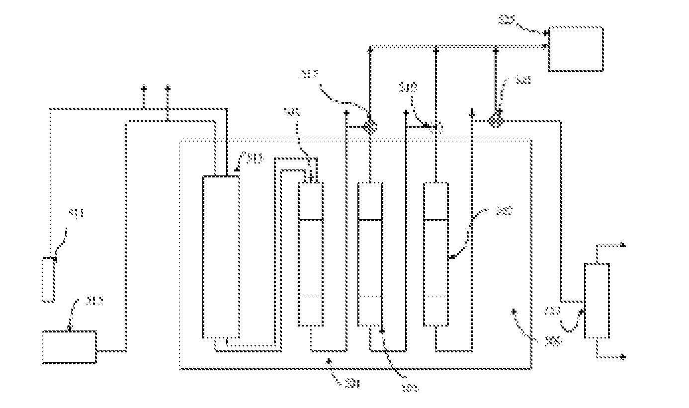
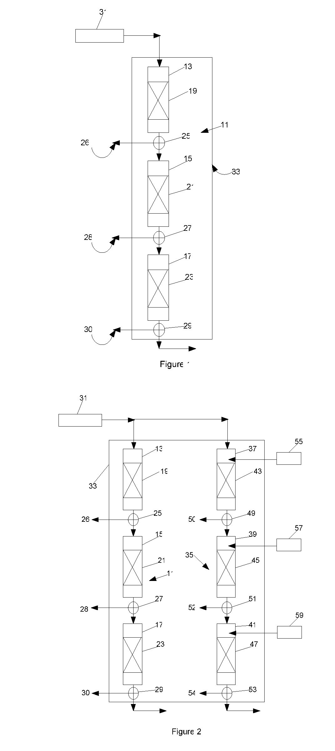
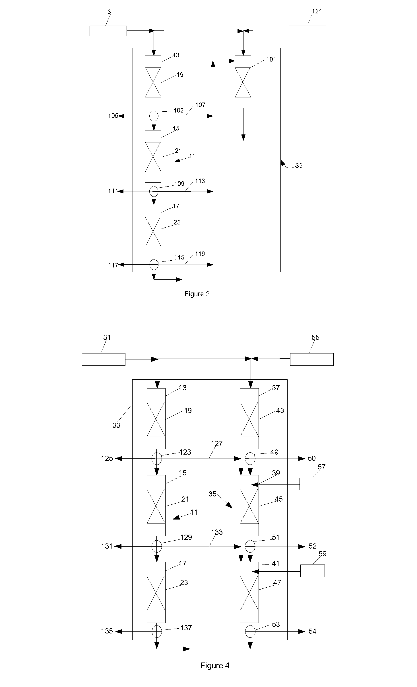
[0034]Referring to FIG. 1 of the drawings, the composite multistage laboratory scale plug flow reactor 11 of a first embodiment of the invention is made up of three series-connected plug flow stages 13, 15 and 17, in this case fixed bed stages, each of which contains a bed of catalyst particles 19, 21 and 23. A sampling valve 25 is connected between the output of the first reactor stage 13 and the input to the second reactor stage 15 and has an output 26 for sampling the effluent from the first reactor stage 13 for analysis. A sampling valve 27 is connected between the output of the second fixed bed reactor stage 15 and the input to the third fixed bed reactor stage 17 and has an output 28 for sampling the effluent from the second reactor stage 15 for analysis. A sampling valve 29 is connected to the output of the third fixed bed reactor stage 17 and has an output 30 for sampling the effluent of the third reactor stage 17 for analysis. The output of the third reactor stage 17 is con...


PUM


Abstract

A method for determining a set of operating parameters for a commercial scale plug flow catalytic process and reactor system for hydroprocessing dirty feedstocks, comprises the steps of: feeding selected partial pressures of said feedstock and hydrogen to the inlet the first reactor stage of a first composite multi-stage series-connected laboratory scale plug flow reactor including at least three reactor stages, the catalyst beds of each of said reactor stages including catalyst particles capable of catalyzing the removal by hydrogen of heteroatoms from said heterocyclic molecules; sampling the effluents of each of said reactor stages; measuring the concentration of heterocyclic molecules in said dirty feedstock in the concentrations of heterocyclic molecules and intermediate and final products and by products of the catalytic reaction in the effluents of each of said reactor stages.

Description

FIELD OF INVENTION[0001]This invention relates to methods for the low cost, accelerated development from discovery to commercial readiness of catalysts and plug flow catalytic processes for hydroprocessing of dirty feedstocks. By the term “dirty feedstocks” is meant feeds such as C10-C20+ distillates from crude oil that contain large heteroatom containing molecules, and cycle oils produced in refinery operations.BACKGROUND OF THE INVENTION[0002]In order to scale-up a plug flow catalytic process for hydroprocessing of dirty feedstocks, it is necessary to define the impact of feedstock composition, time on stream, residence time, catalyst particle size, shape and other characteristics, and temperature profile on reaction rate and selectivity. The first step in a traditional scale-up program generally involves the selection, and definition of the intrinsic properties of, the catalyst. This step is typically performed isothermally with a diluted, crushed or powdered catalyst to minimize...

Claims


Application Information

Patent Timeline
IPC IPC(8): C10G45/72B01L99/00
CPCB01J19/0046C40B60/12B01J2219/00015B01J2219/00286B01J2219/00477B01J2219/00495B01J2219/00585B01J2219/0059B01J2219/00707B01J2219/00747B01J2219/00788B01J2219/00835B01J2219/0086B01J2219/00867B01J2219/00869B01J2219/00873B01J2219/00891B01J2219/00957B01J2219/00961B01J2219/00963B01J2219/00981C10G49/26B01J19/0093
Inventor BAUMAN, RICHARD FFIATO, ROCCO A
Owner ACCELERGY CORP
Why Eureka
Try Eureka