Permanent-magnet-type rotating electrical machine

Active Publication Date: 2010-12-30
KK TOSHIBA
View PDF12 Cites 39 Cited by
  • Summary
  • Abstract
  • Description
  • Claims
  • Application Information

AI Technical Summary

Benefits of technology

[0025]The present invention has been made to solve the above-mentioned problems of the related arts and an object of the present invention is to provide a permanent-magnet-type rotating electrical machine and a permanent magnet motor drive system, capable of conducting variable-speed operation in a wide range from low speed to high speed, realizing high torque in a low rotation speed zone and high output in middle and high rotation speed zones, improving efficiency, reliability, and productivity, and reducing materials, in particular, rare materials.
[0026]Another object of the present invention is to provide methods of easily assembling and disassembling the permanent-magnet-type rotating electrical machine by utilizing the above-mentioned characteristics of the permanent-magnet-type rotating electrical machine.
[0029]The permanent-magnet-type rotating electrical machine provided by the present invention is capable of conducting variable-speed operation in a wide range from low speed to high speed, realizing high torque in a low rotation speed zone and high output in middle and high rotation speed zones, improving efficiency, reliability, and productivity, and reducing materials, in particular, rare materials.
[0030]The methods of assembling and disassembling the permanent-magnet-type rotating electrical machine of the present invention insert the rotor into the inside of the stator, or pull out the rotor from the stator. The methods carry out the assembling or the disassembling in a magnetized state that flux by the first permanent magnet and flux by the second permanent magnet are oppositely oriented at the magnetic pole or the magnetic air gap. Namely, the methods carry out the assembling or the disassembling with a magnetic attraction force that attracts the rotor to the stator weakened. The assembling work or the disassembling work is easily carried out without using large jigs that resist against the magnetic attraction force.
[0031]The permanent magnet motor drive system of the present invention is capable of conducting variable-speed operation in a wide range from low speed to high speed and realizing high torque in a low rotation speed zone and high output and high efficiency in middle and high rotation speed zones.

Problems solved by technology

The rotating electrical machine of the Patent Document 4 is a simple AlNiCo magnet motor, and therefore, provides insufficient output.
Namely, the permanent magnets are hardly magnetized and the flux amount thereof becomes unchangeable.
The voltage induced by the permanent magnets is applied to electronic parts of an inverter, and if the applied voltage exceeds a withstand voltage of the electronic parts, the parts will cause insulation breakage.
Such a design, however, lowers the output and efficiency of the permanent-magnet-type rotating electrical machine in a low-speed zone.
Always passing a negative d-axis current that contributes nothing to an output, however, increases a copper loss to deteriorate efficiency.
Such a voltage increase limits the voltage reduction achieved by the flux-weakening control.
These factors make it difficult for the flux-weakening control to conduct the variable-speed operation for the internal-permanent-magnet-type rotating electrical machine at speeds over three times a base speed.
In addition, the harmonic flux increases an iron loss to drastically reduce efficiency in middle- and high-speed zones.
Further, the harmonic flux generates an electromagnetic force that produces vibration.
The motor in this state produces only a loss to deteriorate an overall operating efficiency.
The motor in this state only produces a loss to deteriorate an overall operating efficiency.
Even if the two kinds of permanent magnets having large and small coercive forces as illustrated in the magnetic characteristic curves of FIG. 7 are employed, the ferrite-based permanent magnets have small coercive force, and therefore, are easily demagnetized to raise the problem of demagnetization even with a magnetic field produced by a q-axis torque current, the necessity of a large current for demagnetization, the problem of insufficient torque, and the like.

Method used


Image

  • Permanent-magnet-type rotating electrical machine
  • Permanent-magnet-type rotating electrical machine
  • Permanent-magnet-type rotating electrical machine

Examples


first embodiment

Permanent-Magnet-Type Rotating Electrical Machine

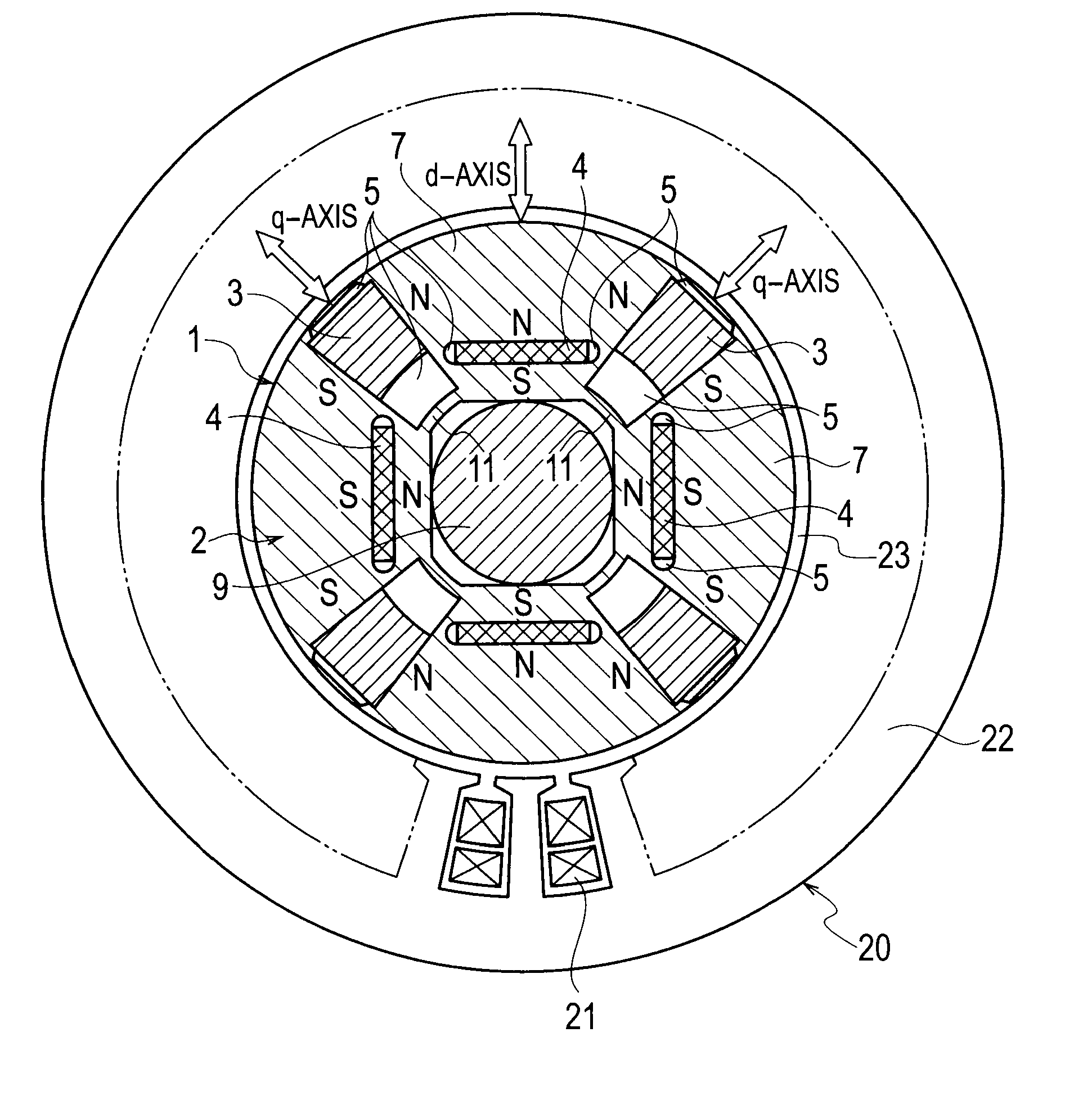
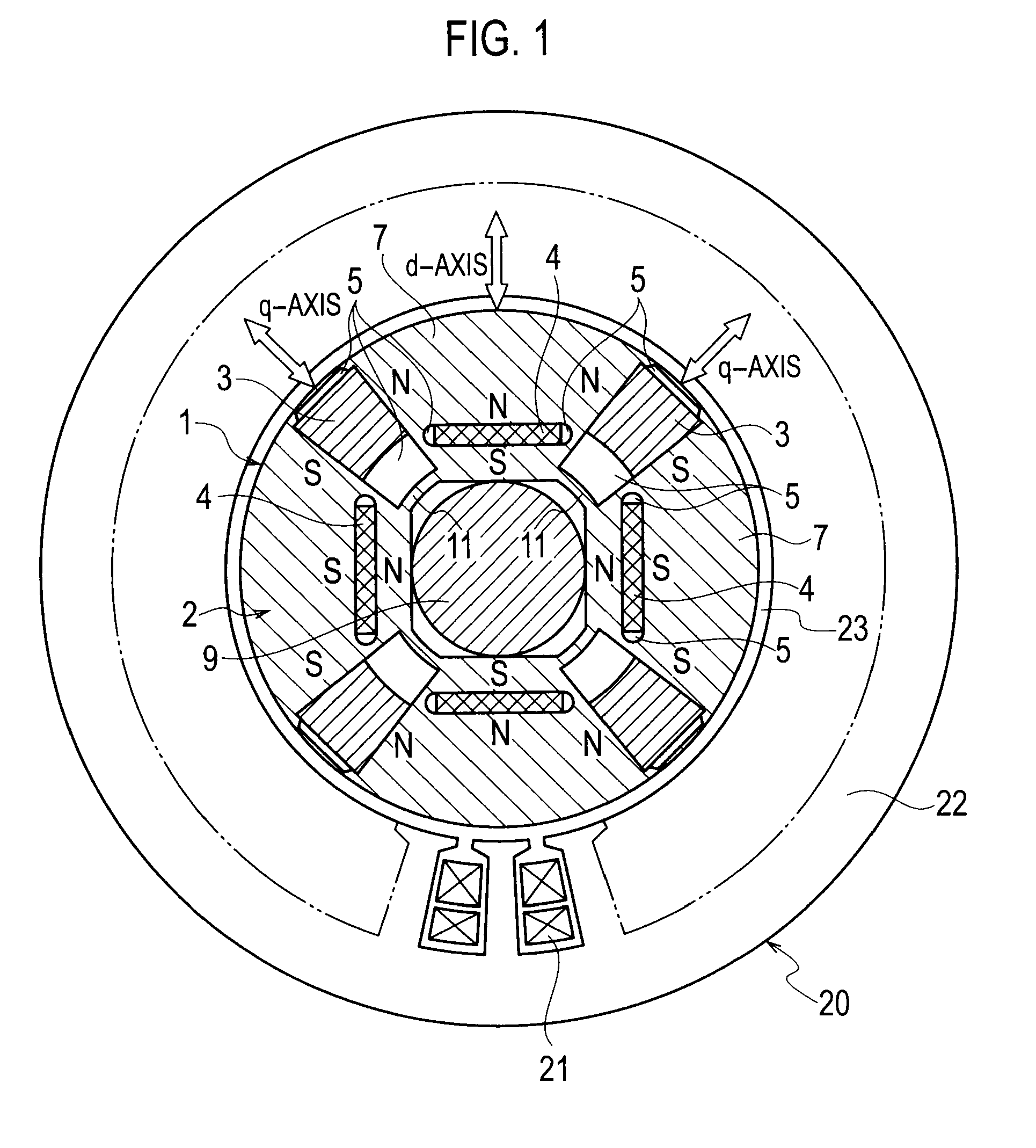
[0053]FIG. 1 illustrates a structure of a permanent-magnet-type rotating electrical machine according to the first embodiment of the present invention. Inside a stator 20, a rotor 1 is accommodated to face the stator 20 with an air gap 23 interposing between them. The stator 20 is a conventional one and is similar to that illustrated in FIG. 20.

[0054]As illustrated in FIG. 1, the rotor 1 in the permanent-magnet-type rotating electrical machine according to the embodiment includes a rotor core 2, first permanent magnets 3 whose product of coercive force and magnetizing direction thickness is small, and second permanent magnets 4 whose product of coercive force and magnetizing direction thickness is large. The rotor core 2 is constituted by laminating silicon steel plates. The first permanent magnet 3 whose product of coercive force and magnetizing direction thickness is small is an AlNiCo magnet and four pieces thereof are embedded in ...

second embodiment

[0122]The second embodiment of the present invention will be explained with reference to FIG. 1. A permanent-magnet-type rotating electrical machine according to the embodiment adopts an AlNiCo magnet as a first permanent magnet 3 having an uneven magnetizing direction thickness and a trapezoidal section as illustrated in FIG. 1.

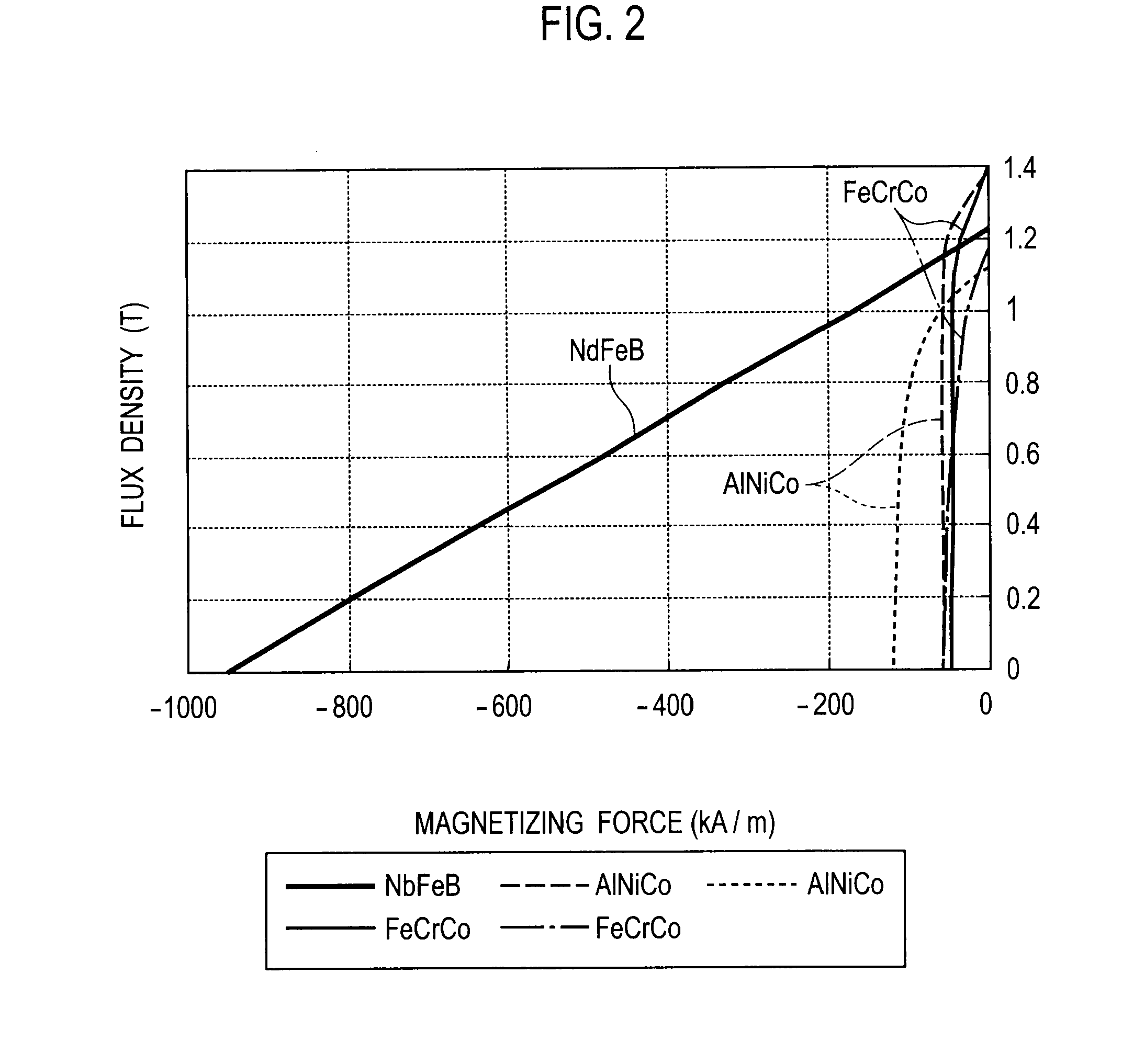
[0123]The AlNiCo magnet has a high remanent flux density and a low coercive force, and therefore, the flux density thereof suddenly changes with respect to a magnetic field in a low flux density zone. Accordingly, finely adjusting the flux density only based on the strength of a magnetic field needs accurately controlling the strength of the magnetic field. For this, the embodiment uses that a magnetizing force needed to magnetize a permanent magnet greatly changes depending on the magnetizing direction thickness of the permanent magnet. According to the embodiment, the AlNiCo permanent magnet 3 is trapezoidal and is uneven in the magnetizing direction thick...

third embodiment

[0124]A permanent-magnet-type rotating electrical machine and permanent magnet motor drive system according to the third embodiment of the present invention will be explained. This embodiment drives the permanent-magnet-type rotating electrical machine 101 illustrated in FIG. 1 by the permanent magnet motor drive system illustrated in FIG. 7 that creates a pulse-like magnetic field with a short-time d-axis current so as to irreversibly magnetize the AlNiCo permanent magnets 3 and change a linkage flux amount. The embodiment always generates flux by a negative d-axis current in a middle or high rotation speed zone, so that linkage flux consisting of the flux by the negative d-axis current and flux by the permanent magnets 3 and 4 is finely adjusted according to the flux by the negative d-axis current. Namely, in the middle or high speed zone, the pulse-like magnetic field created by the short-time d-axis current irreversibly changes the magnetized state of the AlNiCo permanent magnet...


PUM

PropertyMeasurementUnit
Magnetic fieldaaaaaaaaaa
Densityaaaaaaaaaa

Abstract

The present invention provides a permanent-magnet-type rotating electrical machine capable of realizing variable-speed operation in a wide range from low speed to high speed at high output and improving, in a wide operating range, efficiency, reliability, and productivity. A narrow magnetic path 11 is formed in a rotor core 2 of a rotor 1 at an inter-pole yoke that magnetically connects adjacent pole core portions 7 to each other, so that the narrow magnetic path is magnetically saturated with flux of a magnetic field created by a predetermined magnetizing current passed to an armature coil 21. Each of first permanent magnets 3 at each of the pole core portions 7 is magnetized with a magnetic field created by a magnetizing current passed to the armature coil 21, to irreversibly change the flux amount of the first permanent magnet.

Description

TECHNICAL FIELD[0001]The present invention relates to a permanent-magnet-type rotating electrical machine, a method of assembling a permanent-magnet-type rotating electrical machine, a method of disassembling a permanent-magnet-type rotating electrical machine, and a permanent magnet motor drive system.BACKGROUND TECHNOLOGY[0002]Generally, permanent-magnet-type rotating electrical machines are classified into two types. One is a surface-permanent-magnet-type rotating electrical machine having permanent magnets adhered to an outer circumferential face of a rotor core and the other is an internal-permanent-magnet-type rotating electrical machine having permanent magnets embedded in a rotor core. For a variable-speed driving motor, the internal-permanent-magnet-type rotating electrical machine is appropriate.[0003]With reference to FIG. 20, a configuration of a conventional internal-permanent-magnet-type rotating electrical machine will be explained. Along an outer circumference of a r...

Claims


Application Information

Patent Timeline
IPC IPC(8): H02P6/08H02K1/27H02K15/00B23P19/00H02K1/22H02K15/03H02K21/14H02P6/06H02P6/28H02P21/00H02P21/13H02P21/22H02P21/34H02P23/16H02P23/22H02P27/04H02P27/08
CPCH02K1/276H02K1/2766Y10T29/49822Y10T29/49009H02P21/0035H02P21/22
Inventor SAKAI, KAZUTOYUUKI, KAZUAKI
Owner KK TOSHIBA
Why Eureka
Try Eureka