Ms/ms mass spectrometer
a mass spectrometer and mass spectrometer technology, applied in the direction of electron/ion optical arrangement, particle separator tube details, separation process, etc., can solve the problems of deteriorating the quality of the quantitative measurement of the objective component, power supply circuit with a rather complex configuration, etc., to achieve the reduction of noise that appears in the ms/ms spectrum, improve the accuracy of quantitative and qualitative analyses, and high the effect of removing
- Summary
- Abstract
- Description
- Claims
- Application Information
AI Technical Summary
Benefits of technology
Problems solved by technology
Method used
Image
Examples
first embodiment
[0070]One embodiment (first embodiment) of the MS / MS mass spectrometer according to the present invention is hereinafter described with reference to the attached drawings.
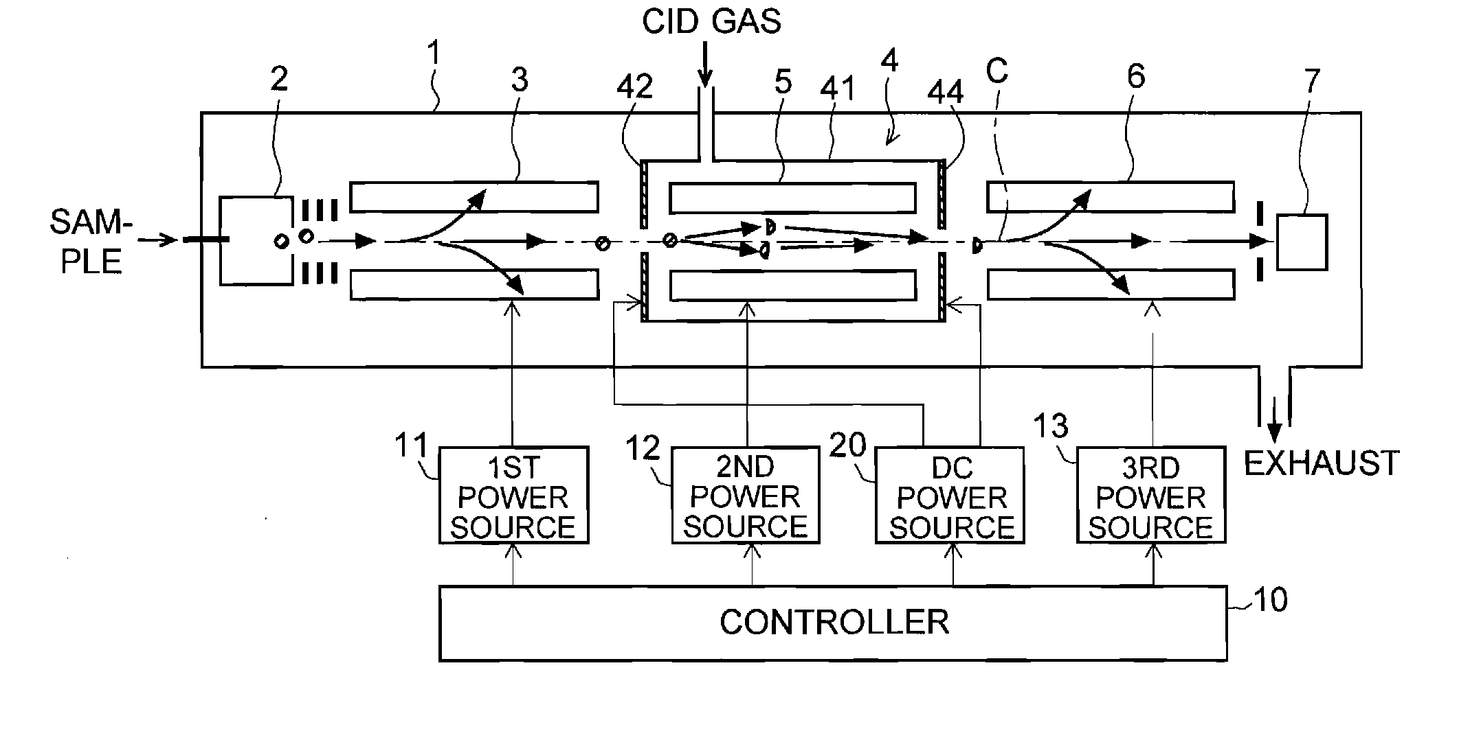
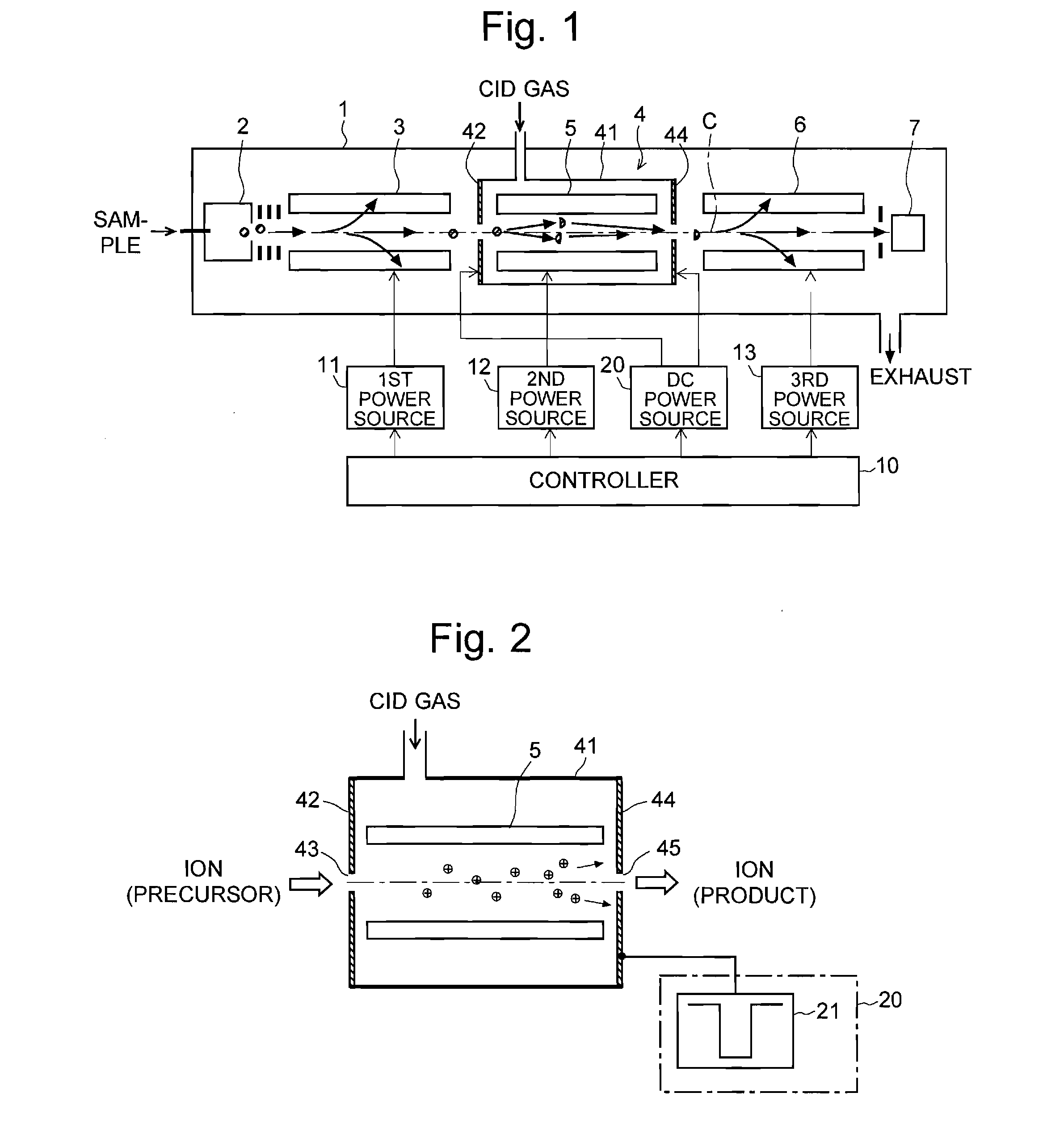
[0071]FIG. 1 is an overall configuration diagram of the MS / MS mass spectrometer of the first embodiment. FIG. 2 is a schematic configuration diagram of the collision cell 4 in FIG. 1 and its control-system circuit. The same components as used in the previously described conventional configuration are denoted by the same numerals and will not be specifically described.
[0072]Similar to the conventional case, the MS / MS mass spectrometer of the present embodiment has a first-stage quadrupole 3 (which corresponds to the first mass separator of the present invention) and a third-stage quadrupole 6 (which corresponds to the second mass separator of the present invention), between which a collision cell 4 for dissociating a precursor ion to produce various kinds of product ions is located, and a second-stage quadrupole 5 s...
second embodiment
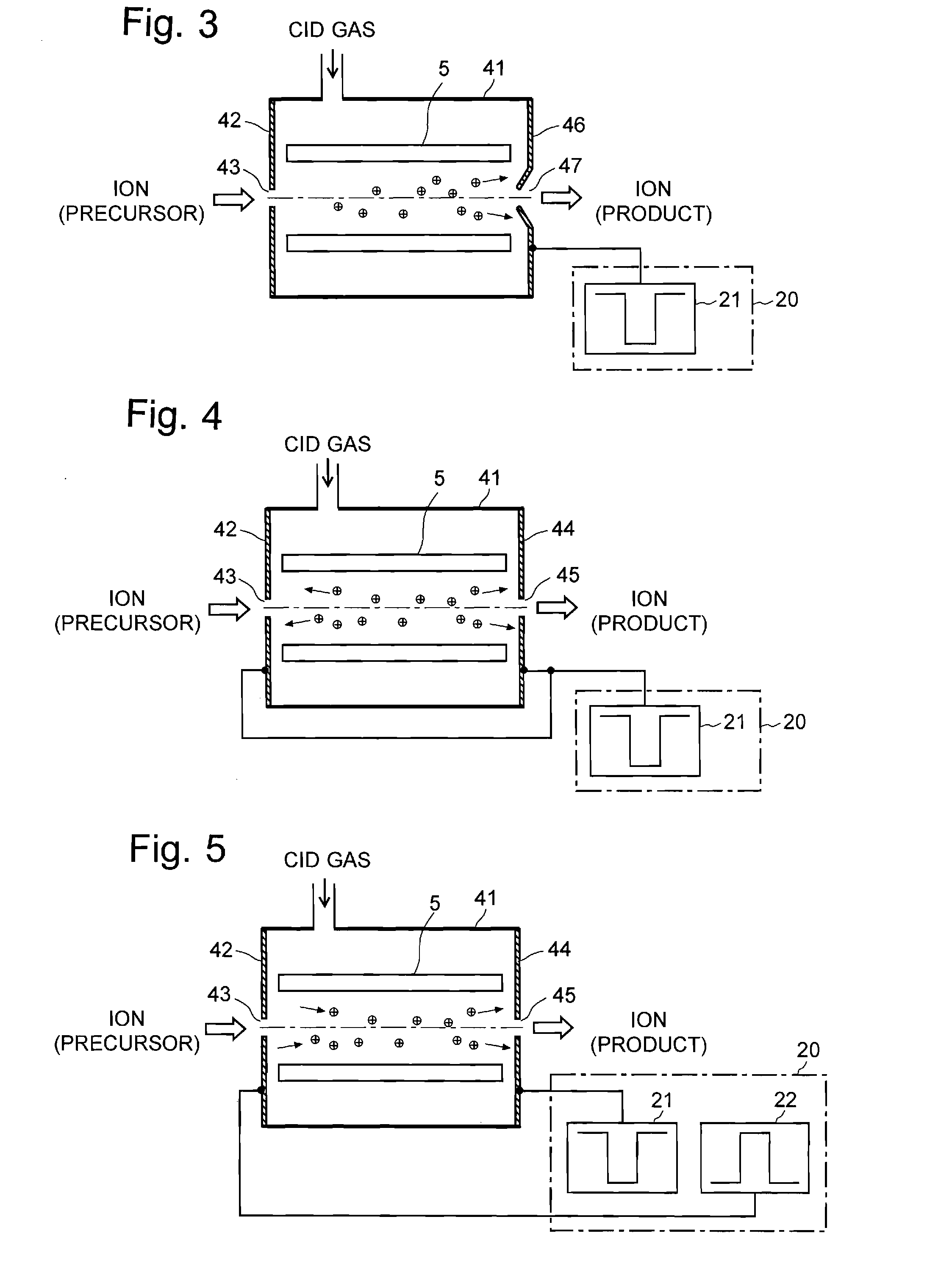
[0081]FIG. 3 is a schematic configuration diagram of the collision cell 4 and its power supply system in the MS / MS mass spectrometer of the second embodiment. In the MS / MS mass spectrometer of the second embodiment, the portion surrounding the aperture 47 of the exit lens electrode 46, to which a negative pulsed voltage is applied, is shaped like a skimmer protruding into the inner space of the collision cell 4. This structure strengthens the ion-pulling DC electric field created in the collision cell 4, so that the ions can be more easily accelerated. Particularly, even if the space surrounded by the second-stage quadrupole 5 is narrow, the effect of the DC electric field can spread over the entire space. This is effective in quickly removing the ions from the collision cell 4.
third embodiment
[0082]FIG. 4 is a schematic configuration diagram of the collision cell 4 and its power supply system in the MS / MS mass spectrometer of the third embodiment. In the MS / MS mass spectrometer of the third embodiment, the same pulsed voltage is applied to both the entrance lens electrode 42 and the exit lens electrode 44. Each of the residual ions within the collision cell 4 is pulled to either the entrance lens electrode 42 or the exit lens electrode 44 and normally to the closer one. Therefore, even an ion existing at positions close to the entrance lens electrode 42 in the collision cell 4 experiences an adequately strong force from the DC electric field. Furthermore, since the distances that the ions need to move to reach the lens electrodes 42 and 44 are short, the residual ions can be more quickly removed from the inner space of the collision cell 4.
PUM
 Abstract
Description
Claims
Application Information
 - R&D
- Intellectual Property
- Life Sciences
- Materials
- Tech Scout
- Unparalleled Data Quality
- Higher Quality Content
- 60% Fewer Hallucinations
Browse by: Latest US Patents, China's latest patents, Technical Efficacy Thesaurus, Application Domain, Technology Topic, Popular Technical Reports.
© 2025 PatSnap. All rights reserved.Legal|Privacy policy|Modern Slavery Act Transparency Statement|Sitemap|About US| Contact US: help@patsnap.com


