Aromatic diamine derivative and organic electroluminescent device using the same

an organic electroluminescent device and diamine derivative technology, applied in the direction of triarylamine dyes, perylene derivatives, anthracene dyes, etc., can solve the problems of device not being put into practical use, device properties deteriorating remarkably, etc., to improve film formability, improve luminous efficiency, the effect of hardly deteriorating

Inactive Publication Date: 2011-01-13
IDEMITSU KOSAN CO LTD
View PDF18 Cites 41 Cited by
  • Summary
  • Abstract
  • Description
  • Claims
  • Application Information

AI Technical Summary

Benefits of technology

[0023]The use of the aromatic diamine derivative of the present invention as a material for an organic electroluminescence device stabilizes the nature of an organic electroluminescence device film and improves film formability. Further, in addition to the advantages, an organic EL device using the aromatic diamine derivative has high luminous efficiency, and hardly deteriorates even when used for a long time period, i.e., has a long lifetime while maintaining its blue color purity.

Problems solved by technology

In addition, the properties of the device deteriorated remarkably, so the device has not been put into practical use.

Method used


Image

  • Aromatic diamine derivative and organic electroluminescent device using the same
  • Aromatic diamine derivative and organic electroluminescent device using the same
  • Aromatic diamine derivative and organic electroluminescent device using the same

Examples


synthesis example 1

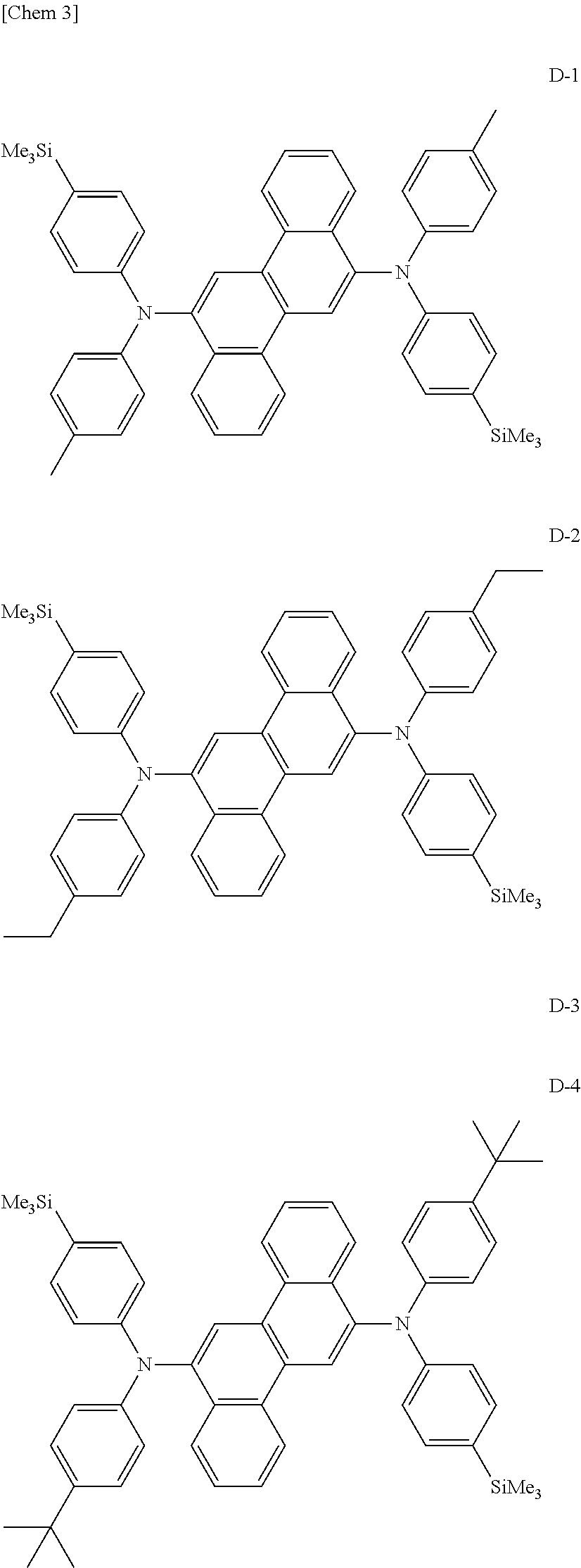
Synthesis of Compound (D-1)

[0115]In a stream of argon, 3.8 g (10 mmol) of 6,12-dibromochrysene, 6.4 g (25 mmol) of N-[4-(trimethylsilyl)phenyl]-N-p-tolylamine, 0.03 g (1.5 mol %) of palladium acetate, 0.06 g (3 mol %) of tri-t-butylphosphine, 2.4 g (25 mmol) of sodium t-butoxide, and 100 mL of dry toluene were loaded into a 300-mL three-necked flask with a cooling tube, and the mixture was stirred under heating at 100° C. overnight. After the completion of the reaction, the precipitated crystal was taken by filtration, and was then washed with 50 mL of toluene and 100 mL of methanol. Thus, 6.0 g of a pale yellow powder were obtained. The resultant powder was identified as Compound (D-1) described above because field desorption mass spectrometry (FD-MS) confirmed that the powder had a ratio m / e of 734.

synthesis example 2

Synthesis of Compound (D-2)

[0116]Synthesis was performed in the same manner as in Synthesis Example 1 except that N-[4-(trimethylsilyl)phenyl]-N-4-ethylphenylamine was used instead of N-[4-(trimethylsilyl)phenyl]-N-p-tolylamine in Synthesis Example 1. The resultant powder was identified as Compound (D-2) described above because FD-MS confirmed that the powder had a ratio m / e of 762.

synthesis example 3

Synthesis of Compound (D-3)

[0117]Synthesis was performed in the same manner as in Synthesis Example 1 except that N-[4-(trimethylsilyl)phenyl]-N-4-isopropylphenylamine was used instead of N-[4-(trimethylsilyl)phenyl]-N-p-tolylamine in Synthesis Example 1. The resultant powder was identified as Compound (D-3) described above because FD-MS confirmed that the powder had a ratio m / e of 790.


PUM

PropertyMeasurementUnit
current densityaaaaaaaaaa
luminanceaaaaaaaaaa
work functionaaaaaaaaaa

Abstract

Disclosed is an aromatic diamine derivative represented by the following general formula (I), which has a chrysene structure in which a phenyl group having a substituted or unsubstituted silyl group is a substituent for an amino group. Also disclosed is an organic electroluminescence device including an organic thin film layer formed of one or more layers including at least a light emitting layer and interposed between a cathode and an anode, in which at least one layer of the organic thin film layer contains the aromatic diamine derivative by itself or as a component of a mixture, the device having a long lifetime and high luminous efficiency. (In the formula, R1 to R10 each independently represent a hydrogen atom, an alkyl group having 1 to 50 carbon atoms, or the like, and R11 represents a substituted or unsubstituted alkyl group having 1 to 50 carbon atoms or the like, and at least one of A, B, and C represents a substituted or unsubstituted silyl group, and the others each represent a hydrogen atom, a substituted or unsubstituted alkyl group having 1 to 50 carbon atoms, or the like, a, b, c, and d each independently represent an integer of 1 to 5.)

Description

TECHNICAL FIELD[0001]The present invention relates to an aromatic diamine derivative and an organic electroluminescence device using the same, in particular, an organic electroluminescence device having a long lifetime and high luminous efficiency, and an aromatic diamine derivative for realizing the device.BACKGROUND ART[0002]A large number of organic electroluminescence (EL) devices each using an organic substance have been developed because of their potential to find applications in solid light emission type, inexpensive, large-area, full-color display devices. In general, an organic EL device is constituted of a light emitting layer and a pair of opposing electrodes between which the layer is interposed. Light emission is the phenomenon in which when an electric field is applied between both the electrodes, an electron is injected from a cathode side and a hole is injected from an anode side, and, further, the electron recombines with the hole in the light emitting layer to prod...

Claims


Application Information

Patent Timeline
Patent Type & Authority Applications(United States)
IPC IPC(8): H01L51/50C07F7/10
CPCC07F7/0818C09B57/00C09B57/001C09B57/008C09B69/008C09K2211/1014C09B3/14C09B3/78C09K11/06C09K2211/1007C09K2211/1011C09B1/00C07F7/081
Inventor MIZUKI, YUMIKOFUNAHASHI, MASAKAZUKAWAMURA, MASAHIROITO, MITSUNORI
Owner IDEMITSU KOSAN CO LTD
Why Eureka
Try Eureka