Circuit for voltage stabilization in an onboard power supply

a technology of voltage stabilization and power supply, which is applied in the direction of electric/fluid circuit, electric devices, transportation and packaging, etc., can solve the problems of too large power loss at the diode, and achieve the effects of high storage density, high efficiency, and rapid reaction

Active Publication Date: 2011-01-20
LISA DRAXLMAIER GMBH
View PDF43 Cites 58 Cited by
  • Summary
  • Abstract
  • Description
  • Claims
  • Application Information

AI Technical Summary

Benefits of technology

[0018]Instead of a battery, in a further embodiment a super capacitor (super cap) may be used as second energy storage, too. Super capacitors are double layered capacitors which can be used as energy storage with a high storage density and which may have capacitance values of several Farads up to several thousand Farads. Super capacitors can store and release energy in a very short time and can thus react very quickly to voltage oscillations in the on-board electrical system. As the super capacitor discharges by itself if the voltage in the on-board electrical system falls below the voltage applied across the capacitor, no switching units for connecting the super capacitor with the on-board electrical system is necessary. It is only necessary to design the capacitor so that when the capacitor is fully charged the voltage generated corresponds approximately to the operating voltage of the on-board electrical system. In idle or normal operating phases in which the power supply of the on-board electrical system is performed by the first energy storage, the super capacitor can be recharged by the first energy storage, or by the generator in the case of a motor vehicle.
[0019]Preferably, the semi-conductor switches of the diode element are field effect transistors, in particular metal oxide semi-conductor field effect transistors (MOSFETs), for example power MOSFETs. As field effect transistors may be switched with low gate voltages and minimum time delay, it is possible to react quickly to changes in the flow of current through the diode element. The field effect transistors connected in parallel may be arranged so that the conduction direction of their intrinsic diodes corresponds to the direction from the first energy storage to the on-board electrical system. Thus, it can be ensured that if the transistors are blocked, no flow of current from the second energy storage to the first energy storage may occur. On the other hand, even with blocked transistors, a portion of the current flowing from the first energy storage to the on-board electrical system may be carried by the intrinsic diodes of the field effect transistors. If the flow of current through the intrinsic diodes increases above a predetermined threshold so that the power losses across the diodes become too large and there is hence the danger of destroying the field effect transistors, the transistors are switched into a conducting state by the pilot and control element. If the voltage at the first energy source drops during the starting operation of a motor vehicle, for example, then the flow current from the connected second energy source to the first energy source is prevented by blocking the transistors.
[0020]In a further embodiment the circuit for voltage stabilization of the on-board electrical system is electrically connected between the on-board electrical system to be stabilized and one or more high-current consumer loads connected to a first energy storage. Thus, the first energy storage can simultaneously or sequentially supply energy to several high-current consumer loads, for example, so that their function is ensured, with voltage drops in the on-board electrical system being prevented by the circuit of the invention.

Problems solved by technology

In this case, a too large power loss would arise at the diode due to the diode's forward bias (forward voltage).

Method used


Image

  • Circuit for voltage stabilization in an onboard power supply
  • Circuit for voltage stabilization in an onboard power supply
  • Circuit for voltage stabilization in an onboard power supply

Examples


first embodiment

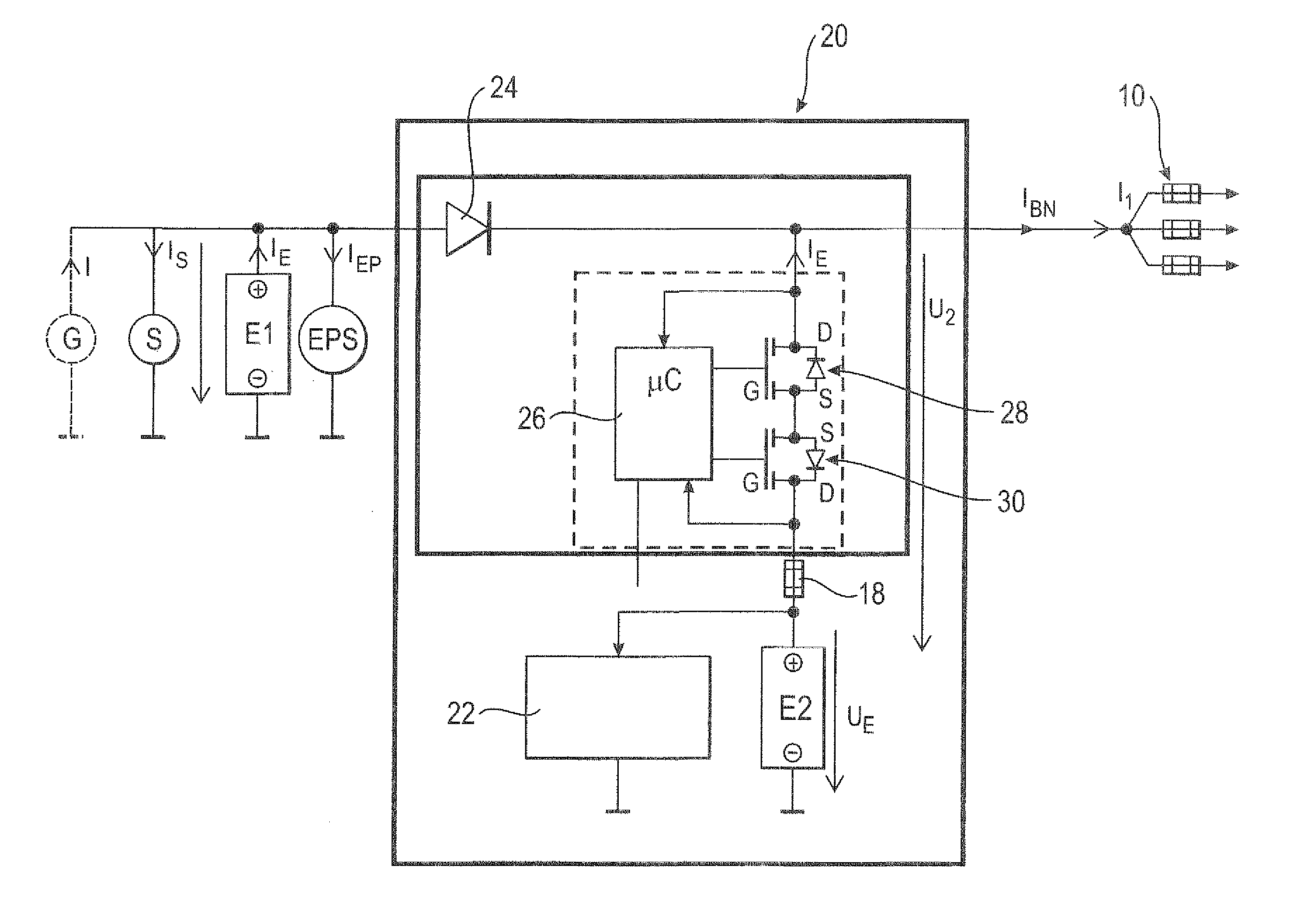
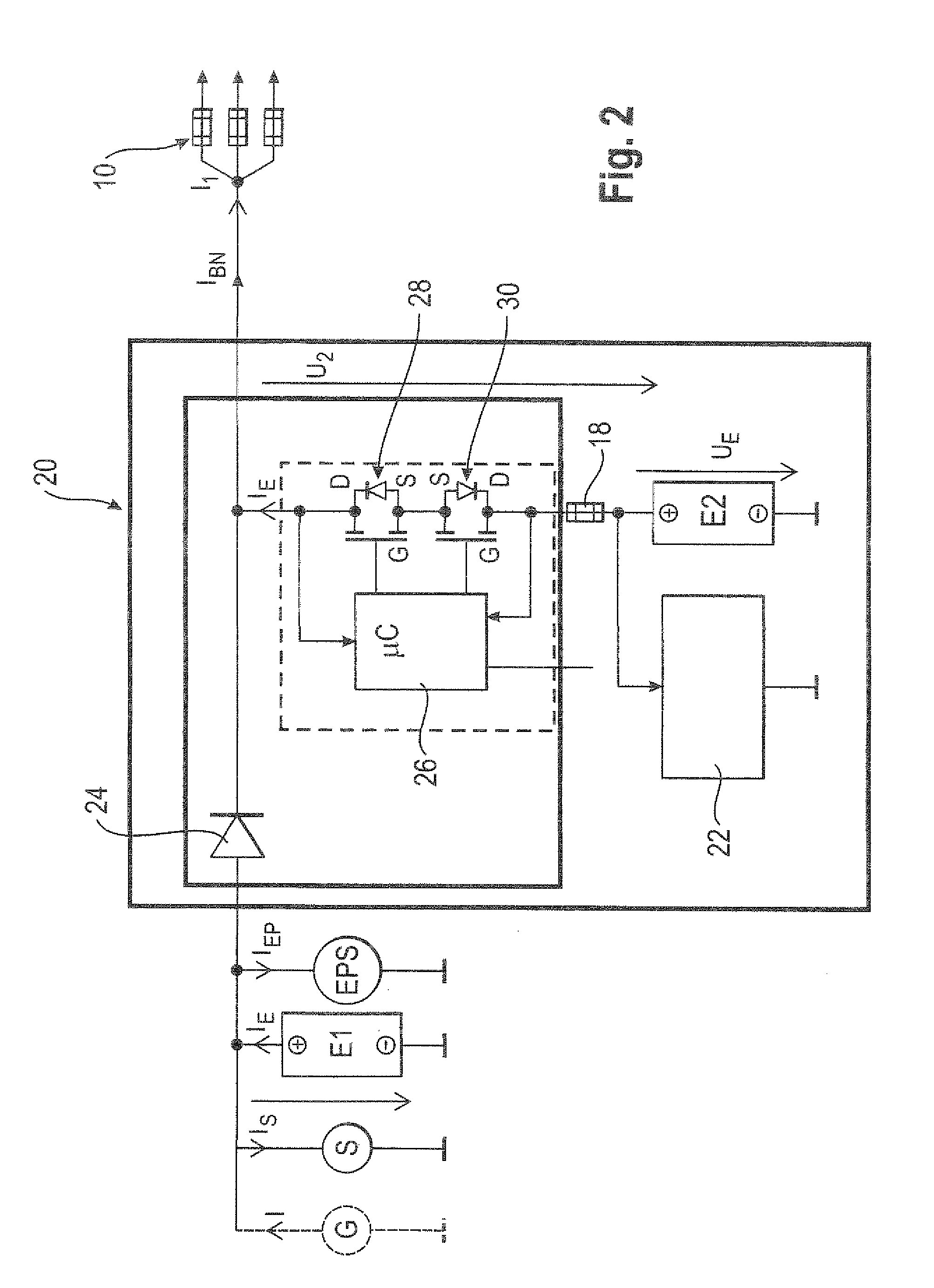
[0030]FIG. 2 shows a circuit 20 for voltage stabilization of an on-board electrical system 10 according to the invention, which is electrically connected between two high-current consumer loads (starter S and EPS system of a motor vehicle) connected with a first energy storage E1 (in this embodiment a battery) and the electrical system 10 to be stabilized. The circuit 20 comprises a diode element 24, a micro-controller 26, two inversely arranged power MOSFETs 28, connected in series, a cutout 18 and a second energy storage E2 (in this embodiment a battery) connected to the on-board electrical system 10 through the cutout 18 and the two power MOSFETs 28, 30. The charging state of the second battery E2 is monitored by an impedance measurement device 22. The micro-controller 26 has the purpose to control the voltages applied at the gate G of the power MOSFETs 28, 30 and, thus, to switch the MOSFETs 28, 30 as desired. Further, the micro-controller 26 measures the voltage and the tempora...

second embodiment

[0032]FIG. 4 shows a circuit diagram of a circuit 50 for voltage stabilization of an on-board electrical system 10 according to the invention. The circuit 50 comprises a diode element 24 constructed as shown in FIG. 3 and a super capacitor 40 (super cap) having a capacity of 110 F.

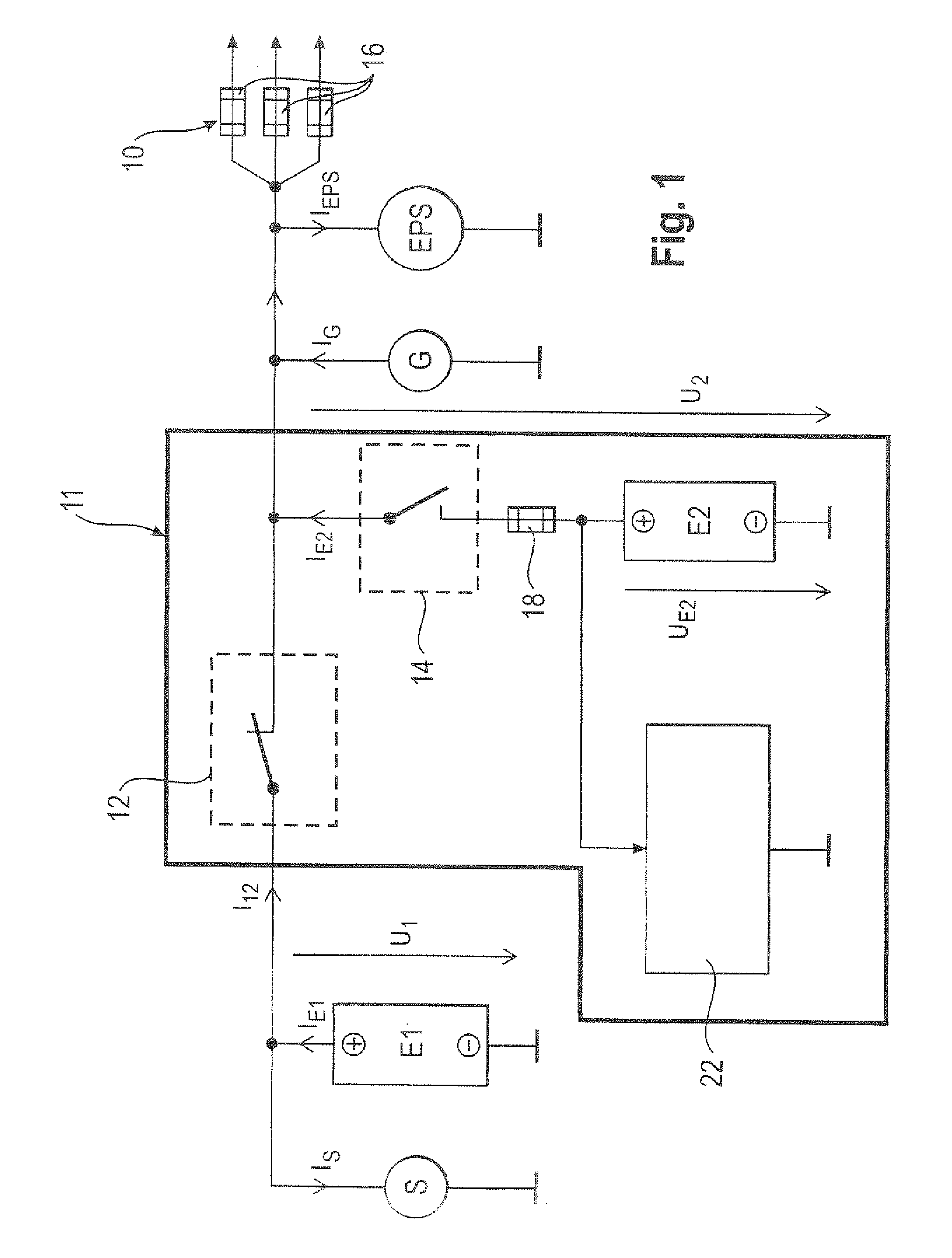
[0033]As explained above, in the circuit 20, 50 of the invention an arrangement of current generator G in front of the diode element 24 (left of the diode element 24 in FIGS. 2 and 4) is possible since an accidental interruption of current flow from the generator G to the on-board electrical system 10 through the diode element 24 is not possible (contrary to the circuit 11 having the cut-off relay 12 shown in FIG. 1). Therefore, the present circuit 20, 50 may also be used in motor vehicles in which the starter S and the generator G are designed as an integrated unit.

[0034]In the following, the mode of operation of the circuit known from the prior art and of the circuit of the invention are explained with t...


PUM


Abstract

The invention relates to a circuit (20, 50) for voltage stabilization in an onboard power supply (10), particularly for motor vehicles, which is electrically connected between the onboard power supply (10) to be stabilized and a first energy store (E1). The circuit (20, 50) comprises a diode element (24) which contains a plurality of semiconductor switches (34) connected in parallel, a pilot and control circuit (33) which determines the level of a current flowing through the diode element (24) and controls the semiconductor switches (34) of the diode element (24) on the basis of the determined current level, and a second energy store (E2) which is electrically connected to the diode element (24) and to the onboard power supply (10).

Description

FIELD OF THE INVENTION[0001]The invention relates to a circuit for voltage stabilization in an on-board power supply (on-board electrical system), which may particularly be used in motor vehicles.PRIOR ART[0002]In modern motor vehicle on-board electrical systems comprising short-time, high-current consumer loads temporary problems in power supply may occur. For example in motor vehicles equipped with a start-stop function which switches off the engine to save fuel, for instance when stopping at traffic lights, the starting operation causes voltage drops. These voltage drops may lead to loss of functionality in several appliances connected to the on-board electrical system. In order to solve this problem, different approaches are known from the prior art.[0003]Document EP 0 987 146 B1 discloses a two-battery system comprising a starter battery loaded only during the starting phase and an on-board power supply battery for power supply of the on-board electrical system. The starter bat...

Claims


Application Information

Patent Timeline
Patent Type & Authority Applications(United States)
IPC IPC(8): B60L1/00
CPCH02J7/1423B60R16/03H02J1/08H02J2310/46
Inventor WORTBERG, MICHAELUHL, GUNTERGROHMANN, DIETER
Owner LISA DRAXLMAIER GMBH
Why Eureka
Try Eureka