Protection of anodes for electrochemical cells

a technology of lithium anodes and anodes, which is applied in the direction of non-aqueous electrolyte cells, cell components, electrochemical generators, etc., can solve the problems of resistive film barriers on the anodes, preventing the commercialization of lithium anodes,

Inactive Publication Date: 2011-01-20
SION POWER CORP
View PDF84 Cites 104 Cited by
  • Summary
  • Abstract
  • Description
  • Claims
  • Application Information

AI Technical Summary

Benefits of technology

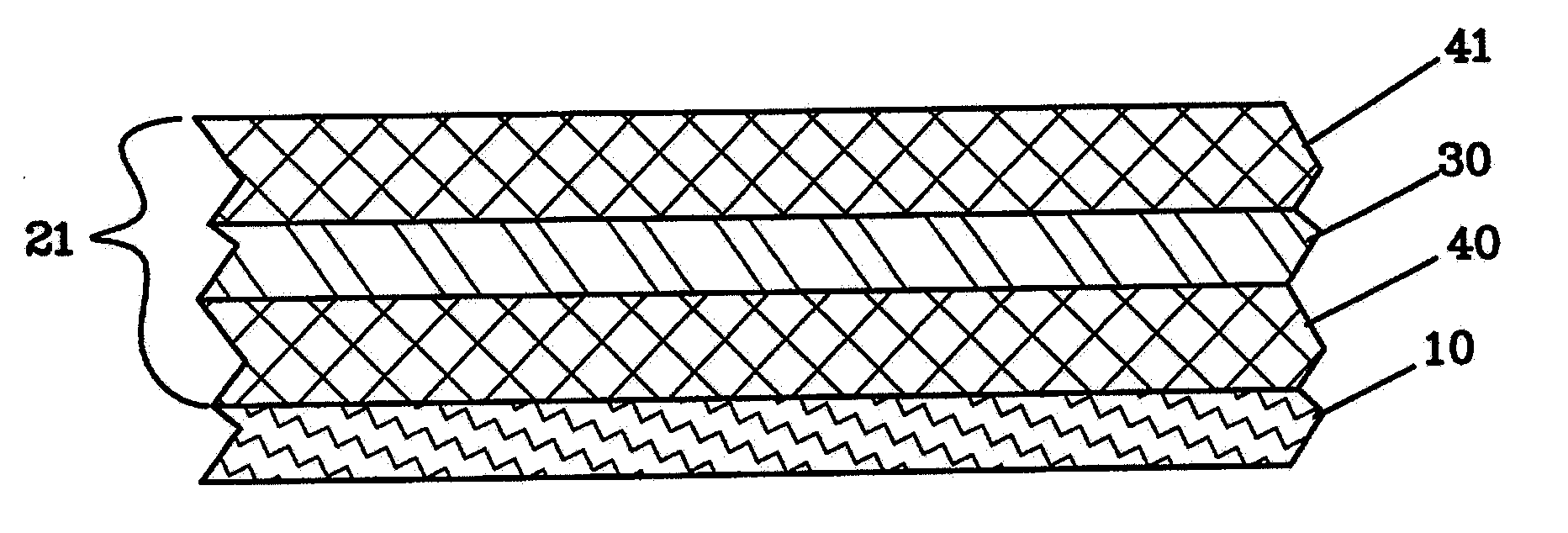
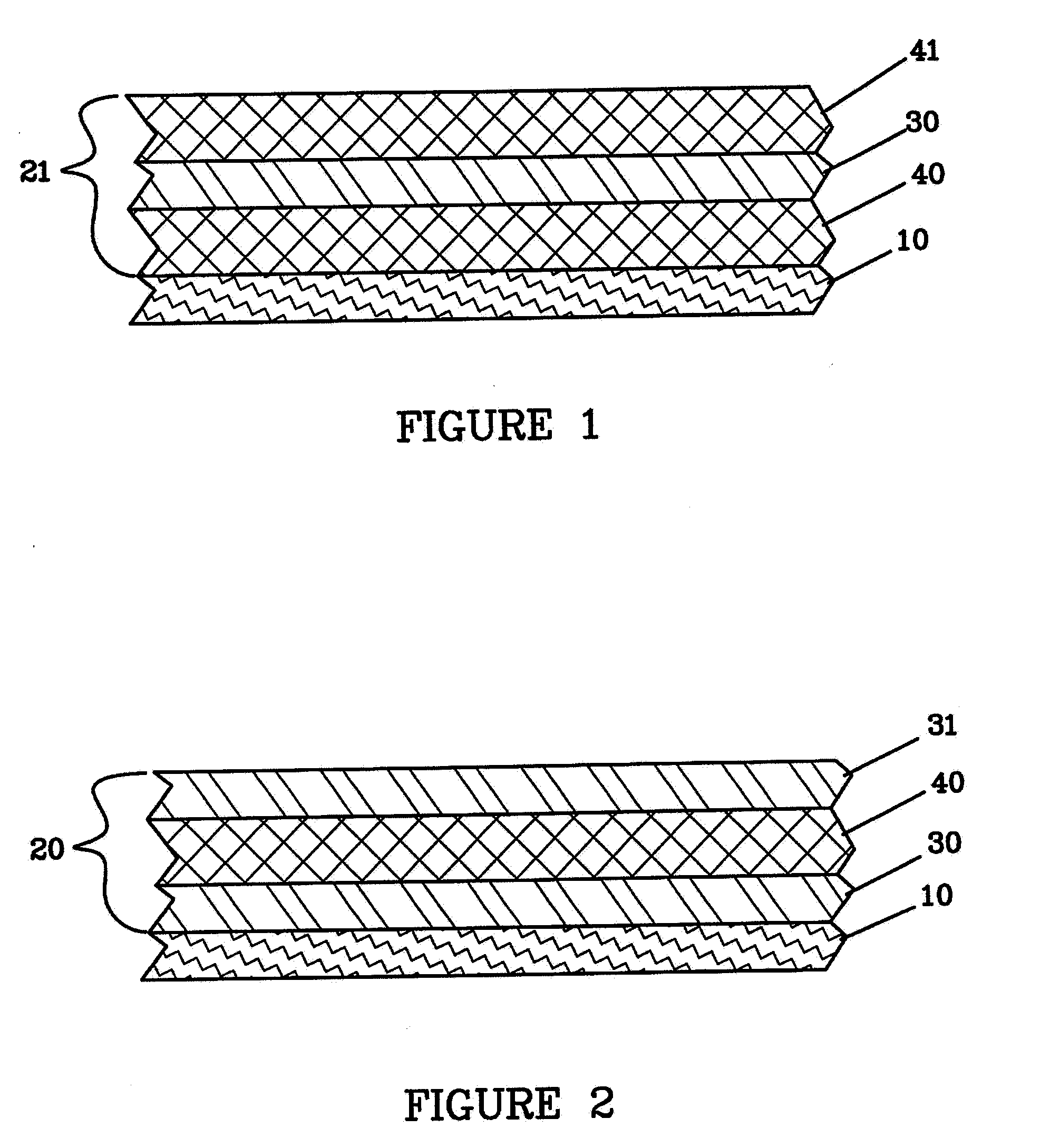
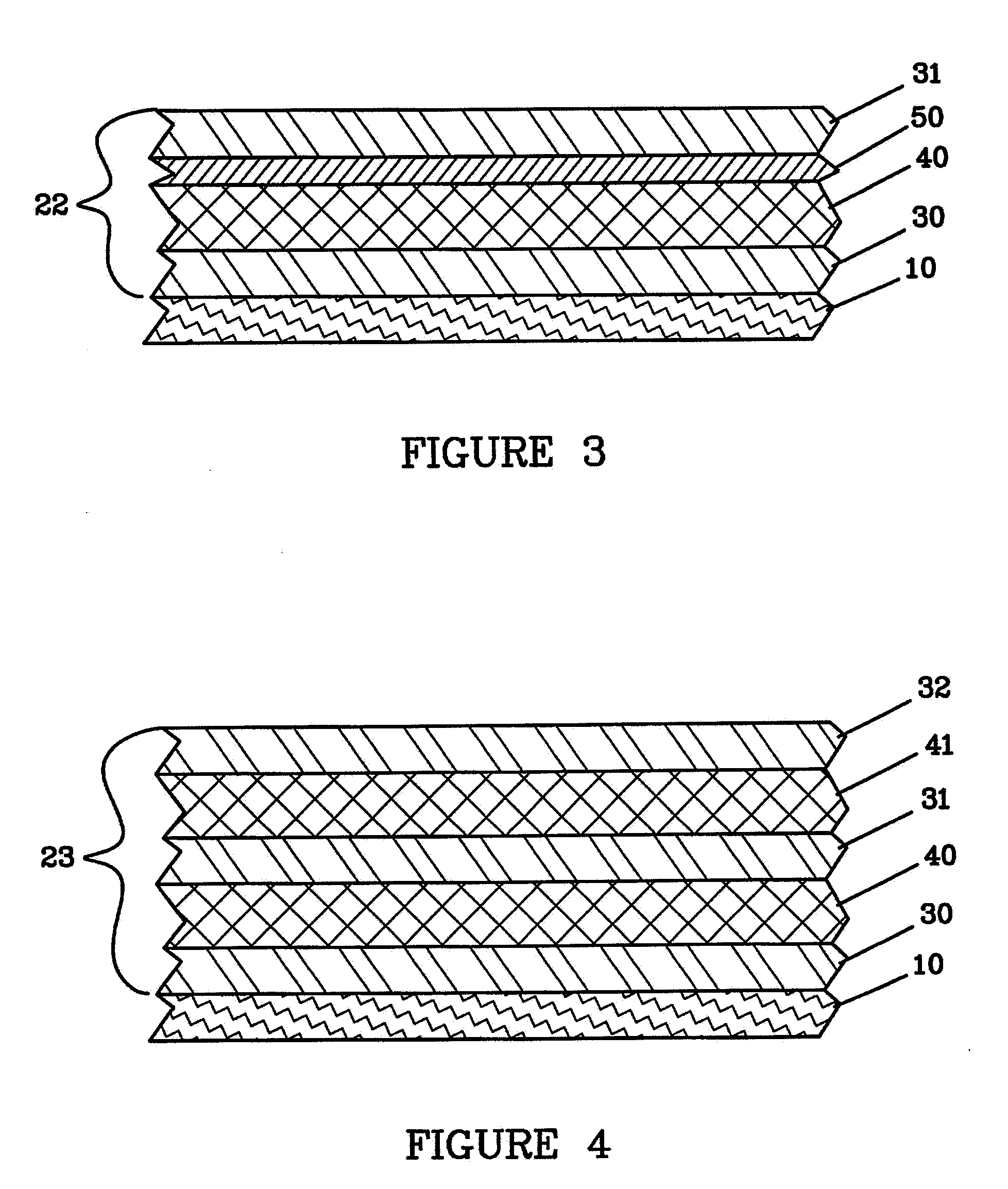
[0011]The anodes may further comprise a substrate, wherein the substrate is in contact with a surface of the first layer on the side opposite to the multi-layer structure, or temporary protective layer. Preferable, the substrate is selected from the group consisting of metal foils, polymer films, metallized polymer films, electrically conductive polymer films, polymer films having an electrically conductive coating, electrically conductive polymer films having an electrically conductive metal coating, and polymer films having conductive particles dispersed therein. Polymer films are especially preferred because of their light weight.

Problems solved by technology

Unfortunately, the reactivity of lithium and the associated cycle life, dendrite formation, electrolyte compatibility, fabrication and safety problems have hindered the commercialization of cells with lithium anodes.
For example, reactions of lithium anodes with the electrolyte may result in the formation of resistive film barriers on the anode.

Method used


Image

  • Protection of anodes for electrochemical cells
  • Protection of anodes for electrochemical cells
  • Protection of anodes for electrochemical cells

Examples


example 1

[0190]A vacuum web coating system located in a dry room, having an unwind drive, liquid cooled drum at −20° C., load cell rollers for controlling tension, a rewind drive, and two deposition zones, was loaded with an anode substrate of 23 μm PET metallized on one side with 60 nm of inconel and of 15 cm width. The chamber was evacuated to 10−6 Ton. Lithium was deposited on to the substrate by first heating a thermal evaporation lithium source to 535° C. to allow significant evaporation, and then starting the web drive at 0.5 feet per minute. The lithium evaporation was allowed to stabilize to give an 25 μm coating of lithium on the inconel of the substrate layer.

example 2

[0191]A vacuum web coating system located in a dry room, having an unwind drive, liquid cooled drum at −20° C., load cell rollers for controlling tension, a rewind drive, and two deposition zones, was loaded with an anode substrate of 23 μm PET metallized on one side with 60 nm of inconel and of 15 cm width. The chamber was evacuated to 10−6 Ton. Lithium was deposited on to the substrate by first heating a thermal evaporation lithium source to 535° C. to allow significant evaporation, and then starting the web drive at 0.5 feet per minute. The lithium evaporation was allowed to stabilize to give an 25 μm coating of lithium on the inconel of the substrate layer. Immediately adjacent to the lithium source CO2 was introduced through a mass flow controller at a flow between 10 and 100 sccm raising the pressure to 0.1 to 50 mTorr. Dark discoloration was immediately seen in the co-deposited lithium with CO2 from this in situ deposition process.

example 3

[0192]A vacuum web coating system located in a dry room, having an unwind drive, liquid cooled drum at −20° C., load cell rollers for controlling tension, a rewind drive, and two deposition zones, was loaded with an anode substrate of 23 μm PET metallized on one side with 60 nm of inconel and of 15 cm width. The chamber was evacuated to 10−6 Ton. Lithium was deposited on to the substrate by first heating a thermal evaporation lithium source to 535° C. to allow significant evaporation, and then starting the web drive at 0.5 feet per minute. The lithium evaporation was allowed to stabilize to give an 25 μm coating of lithium on the inconel of the substrate layer. Immediately adjacent to the lithium source RF magnetron plasma treatment with the CO2 gas was performed. Forward RF power was between 50 and 100 W at a pressure of 0.1 to 50 mTorr. Dark discoloration was immediately seen in the co-deposited lithium with CO2 from this in situ deposition process.


PUM

PropertyMeasurementUnit
metal ion conductivityaaaaaaaaaa
thicknessaaaaaaaaaa
ionic conductivityaaaaaaaaaa

Abstract

Provided is an anode for use in electrochemical cells, wherein the anode active layer has a first layer comprising lithium metal and a multi-layer structure comprising single ion conducting layers and polymer layers in contact with the first layer comprising lithium metal or in contact with an intermediate protective layer, such as a temporary protective metal layer, on the surface of the lithium-containing first layer. Another aspect of the invention provides an anode active layer formed by the in-situ deposition of lithium vapor and a reactive gas. The anodes of the current invention are particularly useful in electrochemical cells comprising sulfur-containing cathode active materials, such as elemental sulfur.

Description

RELATED APPLICATIONS[0001]This application is a divisional of and claims priority to U.S. application Ser. No. 12 / 180,379 filed Jul. 25, 2008, which is a continuation of and claims priority to U.S. application Ser. No. 11 / 781,915 filed Jul. 23, 2007, which is a continuation of and claims priority to U.S. application Ser. No. 09 / 864,890, filed May 23, 2001 (now U.S. Pat. No. 7,247,408), which is a continuation-in-part of U.S. application Ser. No. 09 / 721,578, filed Nov. 21, 2000 (now U.S. Pat. No. 6,797,428), and U.S. application Ser. No. 09 / 721,519, filed Nov. 21, 2000 (now U.S. Pat. No. 6,733,924); both of which claim priority to U.S. Provisional Patent Application Ser. No. 60 / 167,171, filed Nov. 23, 1999, the disclosures of which are incorporated herein by reference in their entirety for all purposes. In addition, U.S. application Ser. No. 12 / 180,379 filed Jul. 25, 2008 is a continuation-in-part of and claims priority to U.S. patent application Ser. No. 11 / 400,025, filed Apr. 6, 20...

Claims


Application Information

Patent Timeline
Patent Type & Authority Applications(United States)
IPC IPC(8): H01M6/18H01M4/58H01M4/00H01M4/60
CPCH01M4/02Y02E60/122H01M4/366H01M4/385H01M4/66H01M4/661H01M10/052H01M10/0562H01M10/36H01M10/4235H01M2004/021H01M2004/027H01M2300/0002H01M2300/0091H01M4/13H01M4/38Y02E60/10
Inventor SKOTHEIM, TERJE A.SHEEHAN, CHRISTOPHER J.MIKHAYLIK, YURIY V.AFFINITO, JOHN D.
Owner SION POWER CORP
Why Eureka
Try Eureka