Rotary joint

a technology of rotary joints and connecting parts, which is applied in the direction of adjustable joints, branching pipes, mechanical equipment, etc., can solve the problems of increasing the amount of supplying refrigerant to the cooling portion, difficult to maintain the supplying refrigerant at cryogenic temperature, and inability to achieve superconducting functions, etc., to achieve the effect of reducing the production cost and assembling cost of the second mechanical seal device and connecting components, reducing the length in an axial

Active Publication Date: 2011-01-27
EAGLE INDS
View PDF2 Cites 10 Cited by
  • Summary
  • Abstract
  • Description
  • Claims
  • Application Information

AI Technical Summary

Benefits of technology

[0022]According to the rotary joint having such constitution, because a large number of second fluid passages can be provided on the rotary seal ring, the supplying refrigerant flowing from one first fluid passage may flow into a plurality of the second fluid passages through the first spaced fluid passage. Then, only a necessary amount of the supplying fluid can be provided to only necessary portions of the respective cooling portions, because the fluid passages of the respective first pipes communicate with a pl

Problems solved by technology

In this rotary joint, a sealing device for sealing relatively rotating communication passages of a fluid passage with a fluid passage at the stationary portion and a fluid passage at the rotary portion, have a problem due to cryogenic temperature associated with the capability of sealing the refrigerant, in order to seal the supplying refrigerant at cryogenic temperature or the discharging refrigerant.
Also, when temperature of the supplying refrigerant rises, the superconducting function cannot be achieved without increasing of the amount of the supplying refrigerant, because it cannot be cooled to a predetermined cryogenic temperature.
Therefore, there is a problem to increase the amount of the supplying refrigerant to the cooling portion.
However, in order to perform the vacuum thermal insulation, it is difficult to maintain the supplying refrigerant at the cryogenic temperature without heightening a degree of vacuum of a space on an outer circumferential side enclosing the fluid passage.
In this vacuum sealing device, since the lubricating capability of seal faces are lost by the vacuum, the seal faces are worn out.
There is a problem that the supplying refrigerant maintained at the cryogenic temperature cannot be supplied to the cooling portion due to a sealing capability of the sealing device.
Under such condition, because it is necessary to supply a large amount of the supplying refrigerant to the cooling portion in order to maintain the cooling portion at the cryogenic temperature, it becomes a problem that a running cost of the supplying refrigerant which is costly is increased.
Also, because a motion gap seal 162 disposed in a cylindrical casing 168 is provided as the inlet cryogenic gas 157 flows on an inner circumferential side and the high temperature cooling gas 164 flows in an outer circumferential side, there is a risk that quality of material deteriorates by the cryogenic temperature to lower the sealing capability.
Particularly, in the constitution of the cryogenic substance transfer joint 26 which has low thermal insulation effect against the outside, because a large amount of inlet cryogenic gas 157 must be su

Method used


Image

  • Rotary joint
  • Rotary joint
  • Rotary joint

Examples


embodiment 1

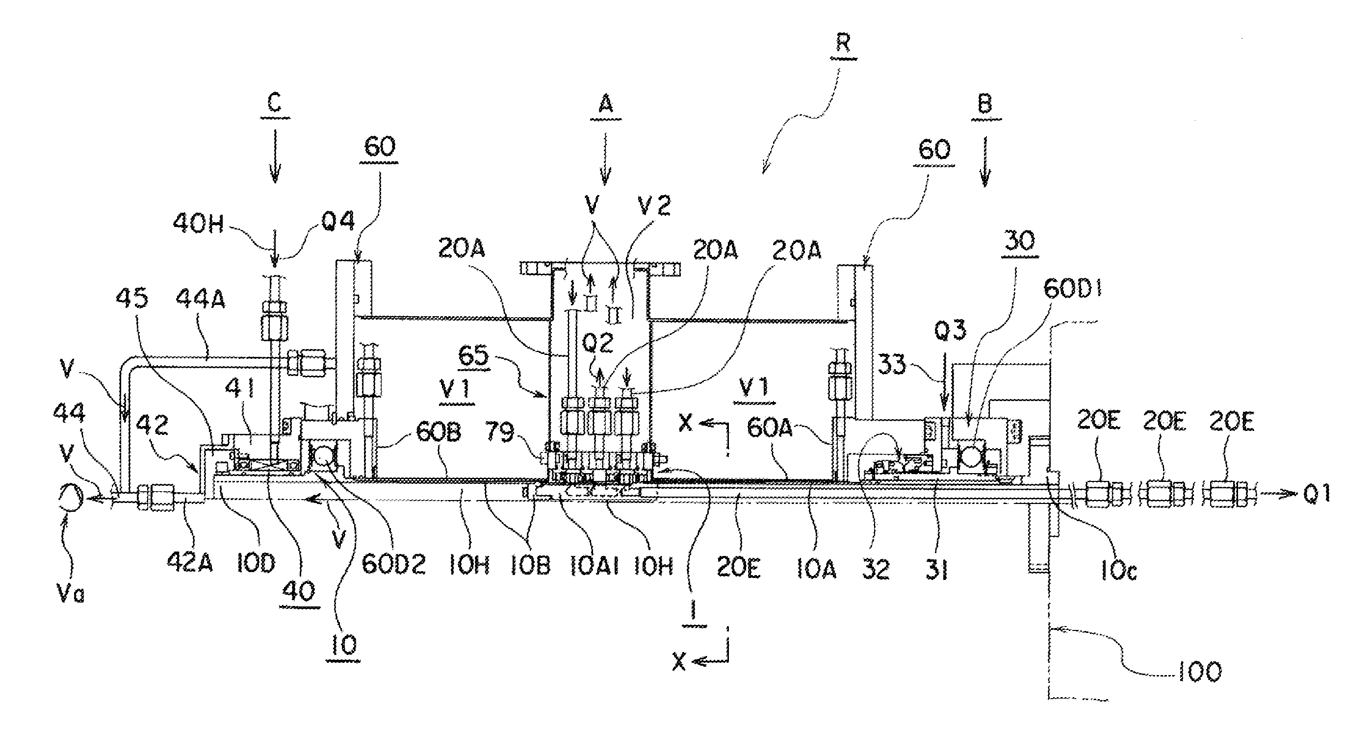
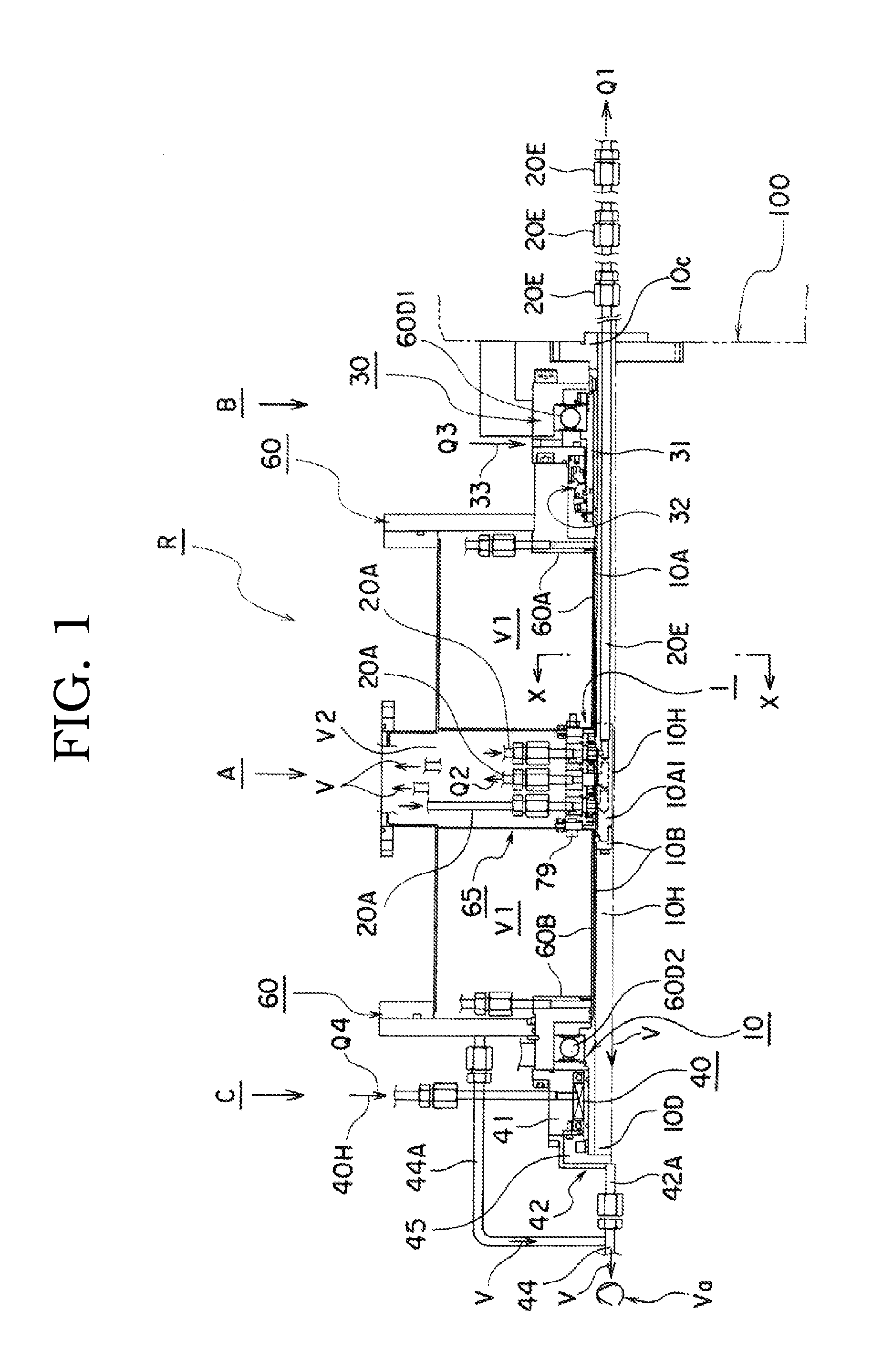
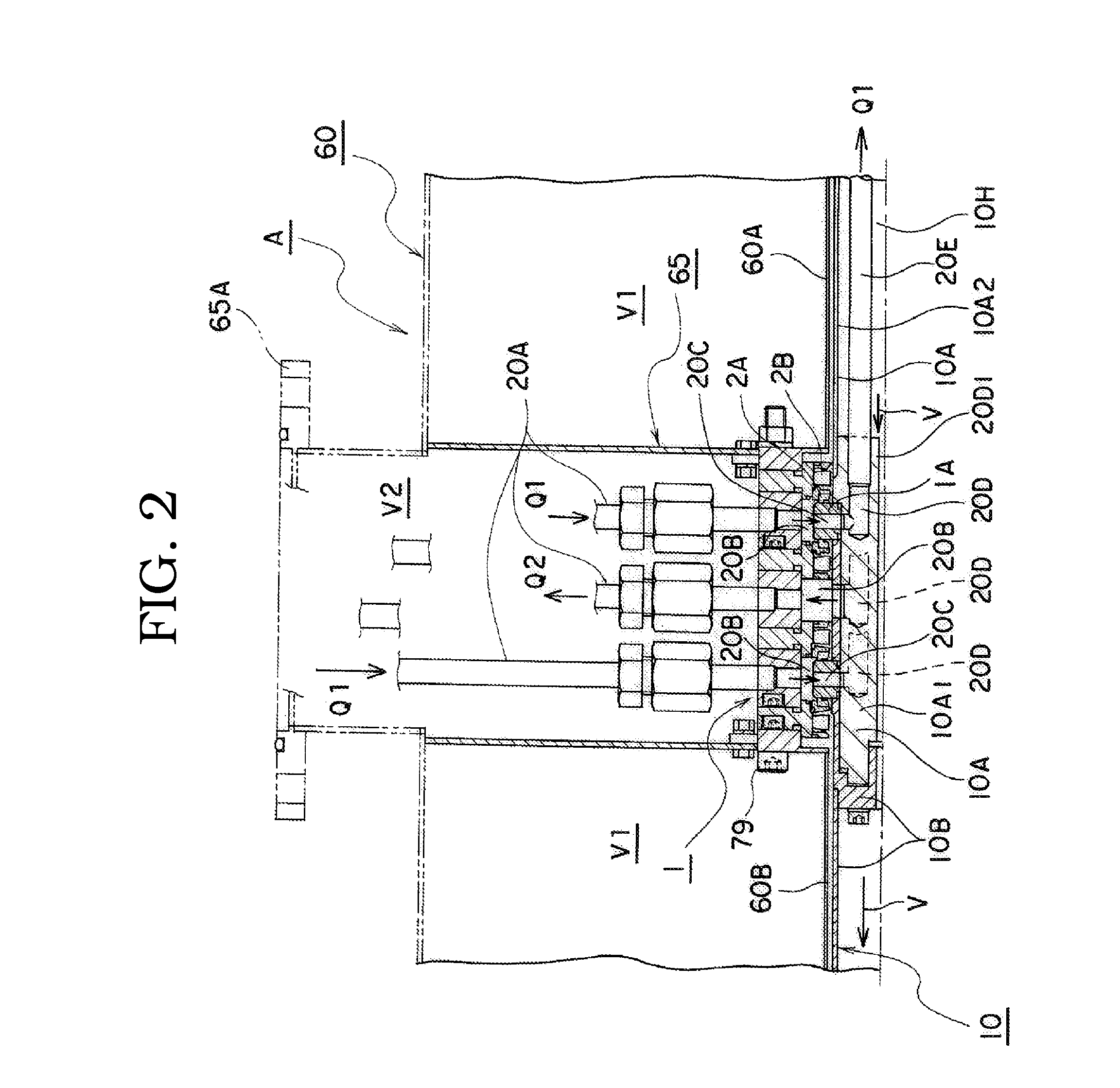
[0033]Note that, each drawing explained blow are accurate drawings produced based on a design drawing. FIG. 1 is a cross sectional view of one side of a rotary joint “R” of the present invention. Note that, in FIG. 1, hatchings are omitted, because the drawing will be unclear, if the hatching is illustrated in the cross sectional view. Also, FIG. 2 shows the vicinity of a mechanical seal device 1 and pipes of FIG. 1, and is an enlarged cross sectional view of one side of a first assembled body “A”. Further, FIG. 3 is a further enlarged cross sectional view showing a constitution of the vicinity of a second mechanical seal device 1 of FIG. 2. FIG. 4 is an enlarged cross sectional view of one side of a second assembled body “B” on a first bearing portion 60D1 side. FIG. 5 is an enlarged cross sectional view of one side of a third assembled body “C” on a magnetic fluid seal 40 side. FIG. 6 is an enlarged cross sectional view of the magnetic fluid seal 40 shown in FIG. 5.

[0034]Below, th...

second embodiment

[0058]FIG. 7 shows a second embodiment and is a front view of the connecting portion 10A1 corresponding to a view in the X-X arrows direction in FIG. 1. This connecting portion 10A1 is formed in a cylindrical shape shorter than the connecting portion 10A1 shown in FIG. 2, and a vacuum passage 10H in a circular shape is formed in an inner circumferential face thereof. Then, in FIG. 7, as similar with the connecting fluid passage 20D shown in the connecting portion 10A1 of FIG. 2, it is formed at 4 or more positions in a radial direction of the connecting portion 10A1 (4 positions in FIG. 4). Respective first pipes 20E is hermetically fitted to connecting bores 20D1 of three of these connecting fluid passages 20D, 20D, 20D. Then, the supplying refrigerant “Q1” is flowed in the first pipes 20E. Further, a second pipe 20E for the discharging refrigerant “Q2” is hermetically fitted to the left 1 position or 2 positions connecting bore 20D1 (for numeral reference, refer to FIG. 2). These ...

embodiment 3

[0060]FIG. 8 is a front view of the rotary seal ring 1A in the axial direction, which is fitted to the vacuum use cylindrical shaft 10. This rotary seal ring 1A is an embodiment 3. The rotary seal ring 1A shown in FIG. 8 is an example wherein the second fluid passages 20C penetrating to the inside thereof are provided at four positions along a circumferential face threreof. An inner circumferential face 1A3 of the rotary seal ring 1A is fitted to the outer circumferential face of the connecting portion 10A1 to communicate the four positions of the second fluid passages 20C with the four positions of connecting fluid passages 20D respectively. Then, the supplying refrigerant “Q1” supplied from the one position of first fluid passage 20A is flowed into the four positions of second fluid passages 20C. Also, respective seal faces 1A1, 1A1 are formed on both end faces of the rotary seal ring 1A. Further, seal mounting grooves 1A4, to which a seal ring 83B shown in FIG. 3 can be mounted, ...


PUM


Abstract

The present invention provides a rotary joint which is available to maintain a cryogenic supplying refrigerant which flows in a fluid passage by a vacuum thermal insulation so that a cooling portion is cooled certainly. The rotary joint of the present invention comprises a vacuum use cylindrical shaft (10) supported in rotatable condition to an inner circumferential face of a main body having a vacuum passage, a rotary seal ring (1A) fitted to an outer circumferential face with a space and provided with seal faces at both end faces, a stationary seal (2A) ring provided at both sides of the respective rotary seal rings and provided with a counter seal face contacting hermetically with the seal face, a resilient bellows (2B) joint with a circumferential face of end portion of the stationary seal ring to press the stationary ring resiliently to the seal face side, a spaced fluid passage (20B) formed between the respective resilient bellows for passing through the supplying refrigerant by joining with a first fluid passage providing the supplying refrigerant, a second fluid passage (20C) communicating with the spaced fluid passage provided at the rotary seal ring, a connecting fluid passage (20D) communicating with the second fluid passage, a first pipe (20E) communicating through the spaced fluid passage so as to provide the supplying refrigerant to be vacuum thermally insulated in the vacuum use cylindrical shaft to a cooling portion, a connecting cover (42) having a suction bore for vacuumizing in the vacuum use cylindrical shaft and a magnetic fluid seal device (40) having a projection constituted as multiple gaps in the axial direction corresponding to a pressure of the vacuumizing.

Description

TECHNICAL FIELD[0001]The present invention relates to a rotary joint with a mechanical seal device provided at an intermediate of a flow passage for a refrigerant to cool a cooling portion as a superconductive magnetic field coil of a superconducting motor and so on by the refrigerant. For more detail, the present invention relates to a rotary joint with a mechanical seal device so as to make available to introduce a supplying refrigerant from a stationary refrigerating machine to a rotary side cooling portion through a relative rotary portion in cryogenic condition.BACKGROUND ART[0002]In a superconducting apparatus such as a superconducting motor and the like, a cryogenic refrigerant such as liquid nitrogen and liquid helium and the like must be supplied to a cooling portion such as a superconducting field coil for maintaining a superconducting status of the super conducting field coil. Also, the refrigerant after use at the cooling portion (referred as “discharging refrigerant”) m...

Claims


Application Information

Patent Timeline
IPC IPC(8): F16L41/00
CPCF16J15/3484F16L27/087H02K5/124H02K55/00Y02E40/62Y02E40/625F16L59/185F16L39/04H02K55/04F16J15/43Y02E40/60
Inventor TAKAHASHI, HIDEKAZUUCHIYAMA, MAMI
Owner EAGLE INDS
Why Eureka
Try Eureka