
Patterning process and resist composition

a resist pattern and resist technology, applied in the field of resist composition, can solve the problems of resist pattern undesired reduction of pattern height or line width, resist pattern misregistration by dry etching, longitudinal shrinkage,

Inactive Publication Date: 2011-02-10
SHIN ETSU CHEM IND CO LTD
View PDF17 Cites 34 Cited by
  • Summary
  • Abstract
  • Description
  • Claims
  • Application Information

AI Technical Summary

Benefits of technology

[0062]The pattern forming process ensures that as a result of double patterning including two exposures, a second resist pattern can be formed in a space portion of a first resist pattern without deformation of the first resist pattern.
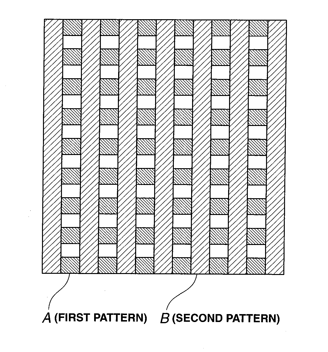
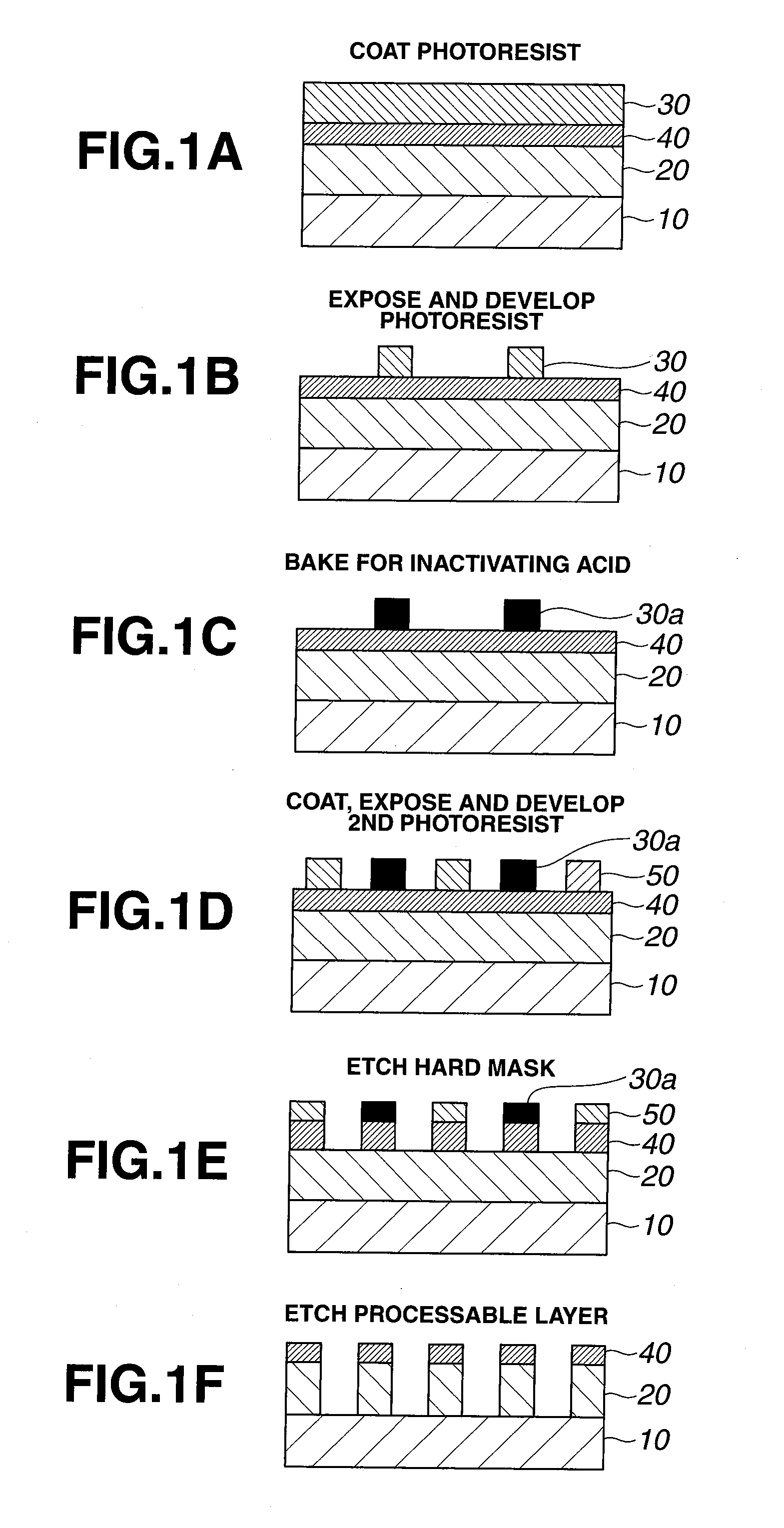
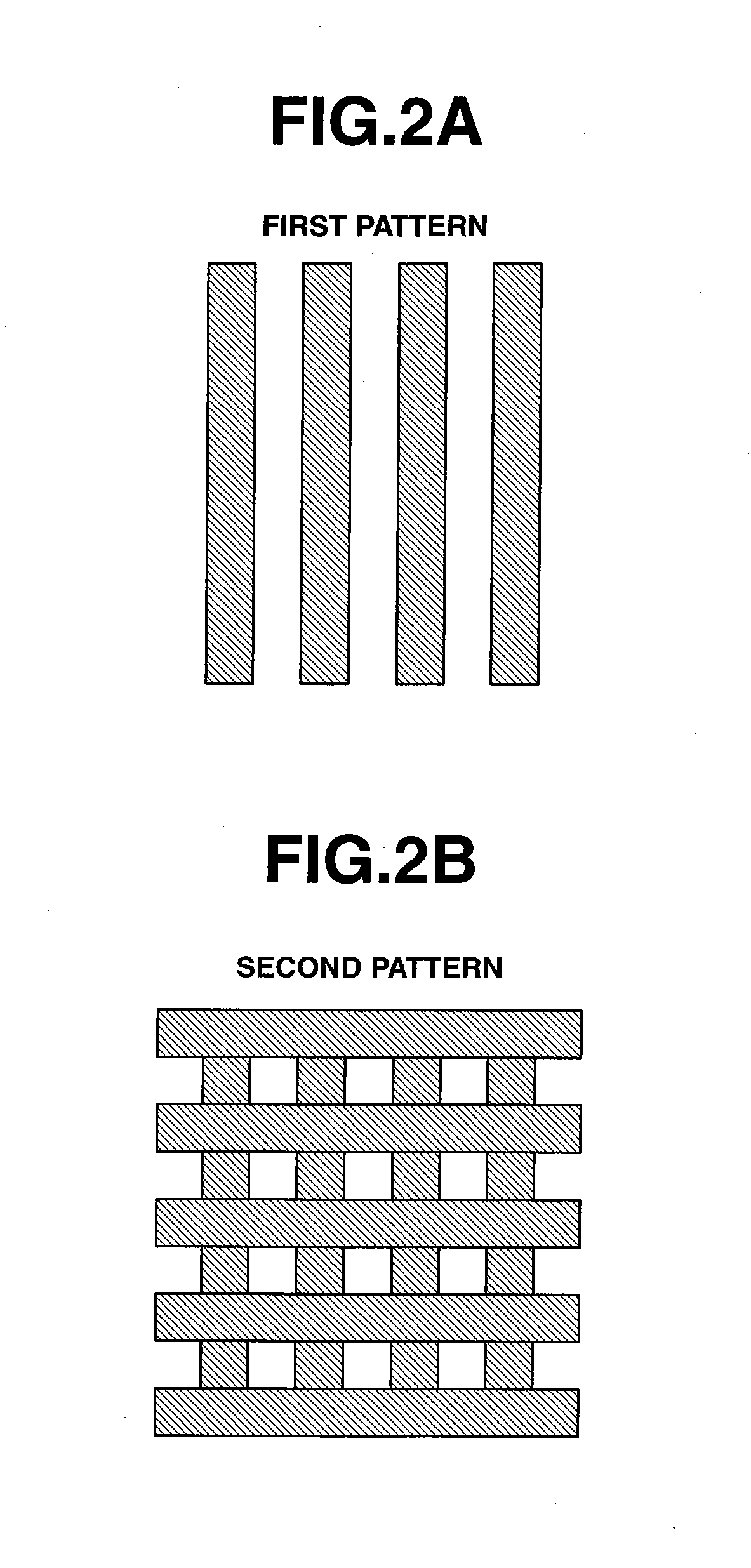
[0063]According to the invention, a pattern is formed by coating a first positive resist composition comprising a copolymer comprising recurring units having lactone as an adhesive group, recurring units having an acid labile group, and recurring units having a carbamate structure onto a substrate to form a first resist film, exposing the first resist film to high-energy radiation, PEB, and developing the first resist film with a developer to form a first resist pattern, heating the first resist pattern to generate a base from the recurring units having a carbamate structure for inactivating the pattern to acid, coating a second positive resist composition comprising a C3-C8 alcohol or a mixture of a C3-C8 alcohol and a C6-C12 ether as a solvent onto the first resist pattern-bearing substrate to form a second resist film, exposing the second resist film to high-energy radiation, PEB, and developing the second resist film with a developer to form a second resist pattern. When the second pattern is formed in an area of the first pattern where first pattern features have not been formed, for example, this double patterning reduces the pitch between pattern features to one half. The substrate can be processed by a single dry etching.

Problems solved by technology

Also an issue of pattern misregistration by dry etchings occurs.
Upon heating and irradiation, the resist pattern undesirably experiences a reduction in pattern height or line width and longitudinal shrinkage.

Method used


Image

  • Patterning process and resist composition
  • Patterning process and resist composition
  • Patterning process and resist composition

Examples


example

[0169]Examples of the invention are given below by way of illustration and not by way of limitation. For all polymers, Mw and Mn are determined by GPC versus polystyrene standards.

synthesis examples

[0170]Polymers to be added to resist compositions were prepared by combining various monomers, effecting copolymerization reaction in tetrahydrofuran medium, crystallization in methanol, repeatedly washing with hexane, isolation, and drying. The resulting polymers (Polymers 1-1 to 1-11, 2-1 to 2-18, Comparative Polymer 1) had the composition shown below. The composition of each polymer was analyzed by 1H-NMR, and the Mw and Mw / Mn determined by GPC.

Preparation of First Resist Composition

[0171]A resist solution was prepared by dissolving each polymer (Polymers 1-1 to 1-11, 2-1, Comparative Polymer 1), an acid generator (PAG1), a base generator (BG1 to 4), a basic compound (amine quencher), and a repellent (for rendering the resist film surface water repellent) in a solvent in accordance with the recipe shown in Table 1, and filtering through a Teflon® filter with a pore size of 0.2 μm. The solvent contained 50 ppm of surfactant FC-4430 (3M-Sumitomo Co., Ltd.). Note that in Comparative...


PUM


Abstract

A pattern is formed by coating a first positive resist composition comprising a copolymer comprising lactone-containing recurring units, acid labile group-containing recurring units and carbamate-containing recurring units, and a photoacid generator onto a substrate to form a first resist film, patternwise exposure, PEB, and development to form a first resist pattern, heating the first resist pattern for inactivation to acid, coating a second positive resist composition comprising a C3-C8 alcohol and an optional C6-C12 ether onto the first resist pattern-bearing substrate to form a second resist film, patternwise exposure, PEB, and development to form a second resist pattern.

Description

CROSS-REFERENCE TO RELATED APPLICATION[0001]This non-provisional application claims priority under 35 U.S.C. §119(a) on Patent Application No. 2009-181504 filed in Japan on Aug. 4, 2009, the entire contents of which are hereby incorporated by reference.TECHNICAL FIELD[0002]This invention relates to a patterning process involving the steps of forming a first resist pattern from a first resist film through exposure and development, heating the first resist pattern to generate a base for inactivation to acid, coating a second positive resist composition comprising a solvent containing a C3-C8 alcohol and an optional C6-C12 ether and not dissolving away the first resist pattern, and forming a second resist pattern in a selected area of the first resist pattern where no pattern features are formed, thereby reducing the distance between pattern features. It also relates to a resist composition used in the process.BACKGROUND ART[0003]In the recent drive for higher integration and operating...

Claims


Application Information

Patent Timeline
IPC IPC(8): G03F7/004G03F7/20
CPCG03F7/0035G03F7/0046G03F7/004G03F7/2041G03F7/0397G03F7/0045G03F7/0047G03F7/095G03F7/20H01L21/027H01L21/0271
Inventor HATAKEYAMA, JUNKATAYAMA, KAZUHIROOHSAWA, YOUICHIOHASHI, MASAKI
Owner SHIN ETSU CHEM IND CO LTD
Learn More