NOx reduction control system for boilers

a technology of nox reduction and control system, which is applied in the direction of furnaces, flue gas purification components, separation processes, etc., can solve the problems of known as “ammonia slip” and achieve the effect of accurate nox reduction

Inactive Publication Date: 2011-02-17
SHALLCROSS JEFF +3
View PDF9 Cites 3 Cited by
  • Summary
  • Abstract
  • Description
  • Claims
  • Application Information

AI Technical Summary

Benefits of technology

[0014]This invention also includes ambient air temperature correction, a method of controlling the NOx formed by measuring the ambient air temperature and adj

Problems solved by technology

Ammonia must be present for the selective catalytic reduction process to occur, however if not controlled, it can lead to wha

Method used


Image

  • NOx reduction control system for boilers
  • NOx reduction control system for boilers
  • NOx reduction control system for boilers

Examples


Embodiment Construction

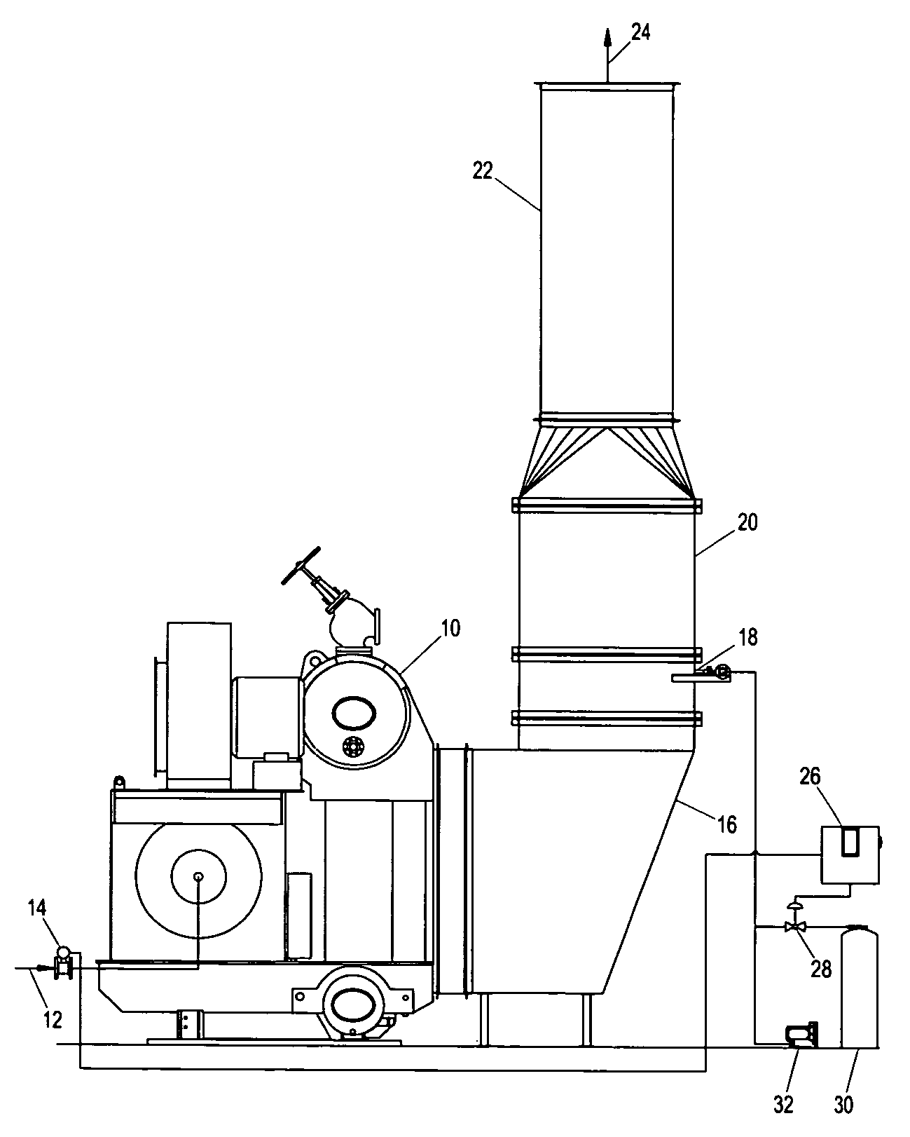
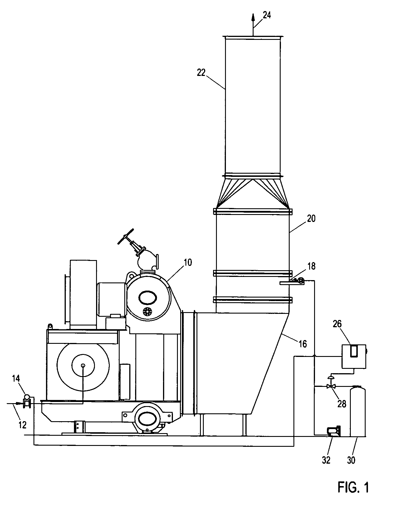
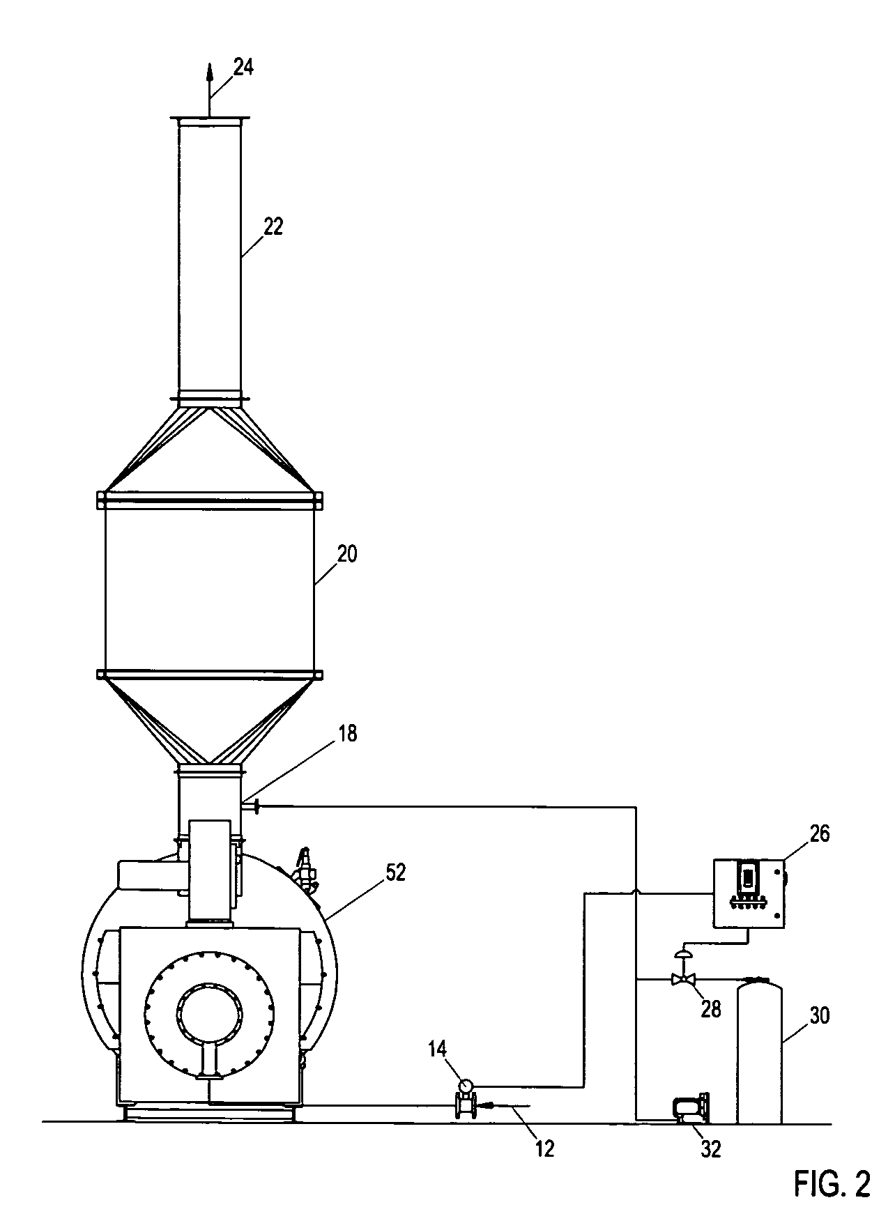
[0021]The invention uses an analog signal directly from a fuel flow device (or similar fuel flow measuring device) to control ammonia for NOx reduction. The control system can also use an alternate analog load signal from the boiler master control, plant master or plant digital control system (better known as a plant or boiler DCS). With the boiler in either manual or automatic operation, the control system receives a signal directly from the fuel flow device indicating the amount of fuel burning and corresponding NOx emissions. The signal is processed using an algorithm with a multi-loop, configurable controller and a mass flow control valve designed with temperature and pressure correction to determine the accurate amount of ammonia to be injected into the flue gas to achieve the desired performance. Air transports the ammonia to an injection grid and subsequently, a mixture of ammonia and flue gas is passed over a catalyst bed, which performs a chemical reaction and reduces NOx e...


PUM

PropertyMeasurementUnit
Fractionaaaaaaaaaa
Temperatureaaaaaaaaaa
Pressureaaaaaaaaaa

Abstract

The invention uses an input signal directly from a fuel flow device to control the amount of ammonia injected into a flue gas stream for NOx reduction for boilers. The control system receives a signal directly from a fuel flow device that indicates the amount of fuel flow and corresponding NOx emissions. The signal is processed using an algorithm with a multi-loop controller and an ammonia mass flow control valve with temperature and pressure corrections to determine how much ammonia must be injected into the flue gas in the presence of a catalyst to achieve the desired NOx emissions reductions. A dilution air blower transports ammonia to an injection grid and subsequently, the ammonia reacts with the flue gas in the presence of a catalyst to reduce the amount of NOx emissions to the desired level.
A bias function that allows a boiler operator to manually increase or decrease the flow of ammonia in order to vary the amount of NOx reduction is included and can be used as an alternate to automatic operation, thus allowing an operator to dictate the amount of ammonia to be injected into the system. Air temperature and pressure correction functions are also included to adjust the ammonia flow based on a given temperature and fuel flow.

Description

CROSS-REFERENCE TO RELATED APPLICATIONS[0001]Not ApplicableSTATEMENT REGARDING FEDERALLY SPONSORED RESEARCH OR DEVELOPMENT[0002]Not ApplicableREFERENCE TO SEQUENCE LISTING, A TABLE, OR A COMPUTER PROGRAM LISTING COMPACT DISK APPENDIX[0003]Not ApplicableBACKGROUND OF THE INVENTION[0004]The embodiment is in the technical field of boiler steam generation emissions control. More particularly, the present invention is in the technical field of controlling the amount of NH3 (ammonia) present as part of a selective catalytic reduction (SCR) system. Selective catalytic reduction is a post-combustion control technology that involves the injection of ammonia in the boiler exhaust gases in the presence of a catalyst to significantly reduce and control airborne contaminants of NOx, the cumulative emissions of nitric oxide (NO) and nitrogen dioxide (NO2) and trace quantities of other nitrogen-bearing species generated during combustion. Ammonia must be present for the selective catalytic reducti...

Claims


Application Information

Patent Timeline
IPC IPC(8): F23J15/04
CPCB01D53/346B01D53/8631B01D2251/2062F23J2219/10F22B37/008F23J15/003F22B35/00
Inventor SHALLCROSS, JEFFREYDAY, LARRYSPAIN, DAVIDSOUZA, JAMES
Owner SHALLCROSS JEFF
Why Eureka
Try Eureka