Concept for optical distance measurement

a technology of optical distance and concept, applied in the direction of distance measurement, diodes, instruments, etc., can solve the problems of difficult precision of distance measurement, limited method speed, and difficult to imagine, so as to increase the measuring speed, double the measuring speed, and halve the laser energy

Active Publication Date: 2011-02-17
VOLKSWAGEN AG
View PDF13 Cites 104 Cited by
  • Summary
  • Abstract
  • Description
  • Claims
  • Application Information

AI Technical Summary

Benefits of technology

[0027]Preferred embodiment s of the present invention allow using only one laser pulse for recording the time delay Td of the pulse or the distance information d resulting from this completely. This allows halving the laser energy needed compared to conventional art and, at the same time, doubling the measuring speed. This results in an optimum correlation possible of distance and normalization measured values (reflectivity, attenuation caused by distance), which is why the inventive concept is also suitable for scenarios of strong temporal variations and/or very quickly moving objects.
[0028]In a pixel structure in accordance with a preferred embodiment of the present invention, the ambient light may be recorded nearly at the same time as the sig

Problems solved by technology

In particular in the consumer field, digital and cell phone cameras have developed to become a mass product and it is hard to imagine these not to be there.
However, superpositioning useful signals Elight,source,r and ambient light Eamb makes exact determination of the runtime delay Td and thus the precision of the distance measurement extremely difficult.
All in all, two corresponding laser pulse cycles are needed for determining a distance, which, on the one hand, limits the speed of the method and, on the other hand, increases the laser energy needed.
Additionally, the temporal off

Method used


Image

  • Concept for optical distance measurement
  • Concept for optical distance measurement
  • Concept for optical distance measurement

Examples


Embodiment Construction

[0041]Before the present invention is discussed in detail referring to FIGS. 4 to 7, it is pointed out that same elements in the figures are provided with same or similar reference numerals and that a repeated description of these elements is omitted.

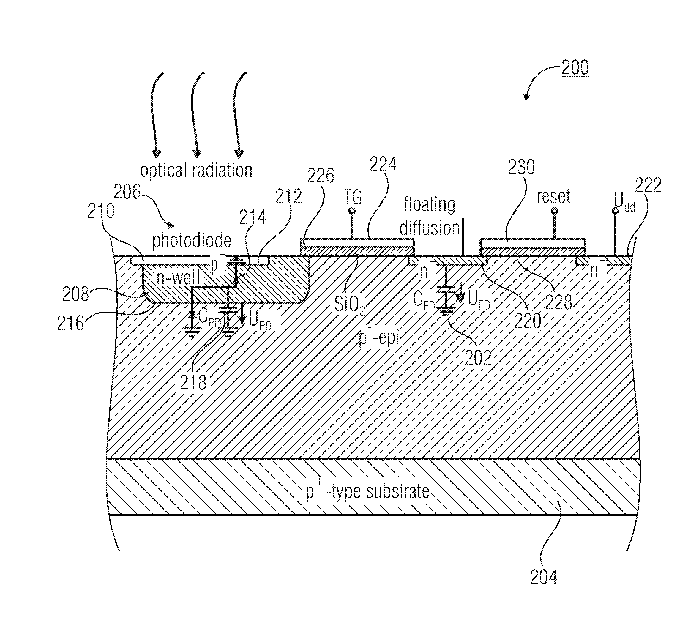
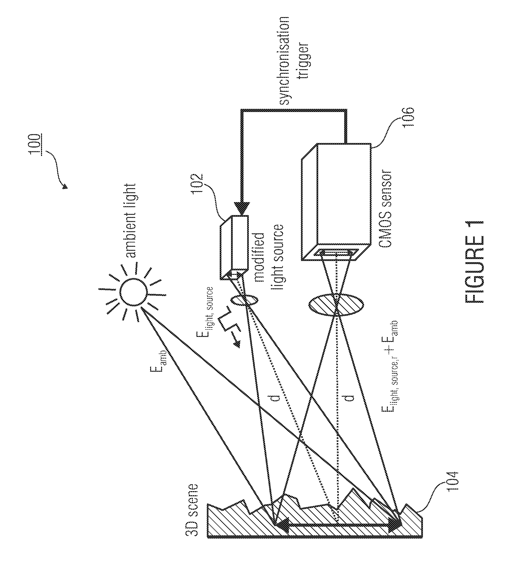
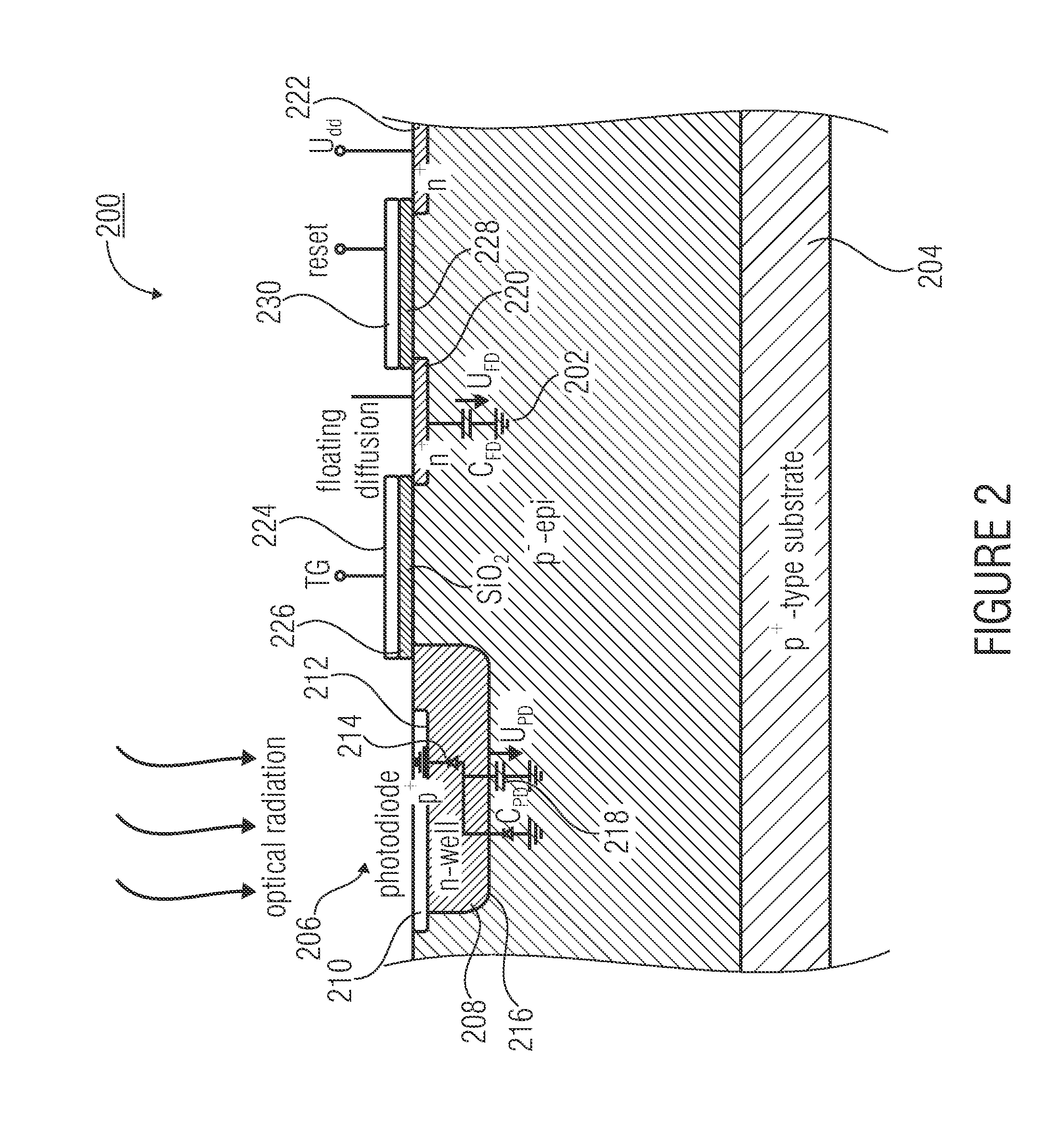
[0042]Additionally, it is pointed out that, in the following description of the figures, it is assumed that the pixel structures shown are a part of a system for optical distance measurement, similar to FIG. 1, which is why reference is partly made to FIG. 1 and the elements thereof, without repeating the description of the setup of FIG. 1. In particular, the pixel structures described below may exemplarily represent a single pixel of a pixel array of an image sensor 106, as will become apparent from the following description.

[0043]FIG. 4 shows a pixel structure 400 in accordance with a preferred embodiment of the present invention in a schematic top-view illustration.

[0044]The pixel structure 400 comprises a photoactive or photo-sensit...


PUM


Abstract

The present invention relates to a concept for optical distance measurement, wherein a radiation pulse is emitted in the direction of an object of measurement. At least two different transfer gates which couple a photoactive region to at least two different evaluating capacities are driven during different drive intervals so that charge carriers generated during the drive intervals by a radiation pulse reflected from the object of measurement and/or by ambient radiation can be transported from the photoactive region to the evaluating capacities each coupled to the at least two transfer gates. Another transfer gate is driven during a time outside the drive intervals of the at least two transfer gates to connect the photoactive region to a reference potential terminal acting as a charge carrier sink during the time outside the drive intervals of the at least two transfer gates.

Description

CROSS-REFERENCE TO RELATED APPLICATION[0001]This application claims priority from German Patent Application No. 10 2009 037 596.1, which was filed on Aug. 14, 2009, and is incorporated herein by reference in its entirety.BACKGROUND OF THE INVENTION[0002]The present invention relates to a concept for optical distance measurement, as may exemplarily be used in so-called ToF (Time of Flight) three-dimensional imaging.[0003]There are various applications in which optical radiation is to be detected. Cheap CMOS (Complementary Metal-Oxide Semiconductor) image sensors and camera systems have become standard elements of everyday life. In particular in the consumer field, digital and cell phone cameras have developed to become a mass product and it is hard to imagine these not to be there. In the field of special applications as well, cheap CMOS cameras are becoming more and more interesting compared to high-quality but considerably more expensive CCD (Charge-Coupled Device) image sensors. I...

Claims


Application Information

Patent Timeline
IPC IPC(8): G01C3/08G01S7/4863G01S17/10G01S17/894
CPCG01S7/4863H01L27/14643G01S17/89G01S17/10G01S17/894
Inventor SPICKERMANN, ANDREASBROCKHERDE, WERNERHOSTICKA, BEDRICH J.
Owner VOLKSWAGEN AG
Why Eureka
Try Eureka