Method and device for particle removal and droplet preparation for qualitative and quantitative bioanalysis

a bioanalysis and particle technology, applied in chemical methods analysis, filter regeneration, material testing goods, etc., can solve the problems of difficult to clean plasma, interfere with assay procedures, and separate equipment and technicians' time for separation of rbc, etc., to achieve rapid plasma yields

Inactive Publication Date: 2011-02-24
ADVANCED MICRODEVICES PVT
View PDF8 Cites 14 Cited by
  • Summary
  • Abstract
  • Description
  • Claims
  • Application Information

AI Technical Summary

Benefits of technology

[0022]An object of the present disclosure is to provide a particle removal and droplet preparation device for separating RBC from blood and to rapidly achieve high yields of plasma with minimum use of whole blood.

Problems solved by technology

Generally, the presence of particulates and cellular matter in the fluids interfere with the assay procedures.
However, the conventional methods suffer from the disadvantage that they require separate equipment and technician time for separation of RBC.
They also require availability of larger volume of patient sample, as plasma is difficult to separate cleanly from very small quantity of samples of blood.
The above-mentioned factors make the conventional methods unacceptable for ‘point of care’ (POC) or ‘near patient’ applications, which involve rapid test results with user-friendly equipments used by minimally trained staff.
Many of the above inventions suffer from the fact that the fluid path for sample fluid is relatively short in the transverse direction resulting in low efficiencies of retention and leakage of particulate matter.
Due to short path lengths, not only do these devices suffer from poor retention but the free or pure plasma is not available as there is no provision to remove the pure plasma from the matrix.
It is well known that when whole blood is filtered by applying pressure, it has to be done extremely slowly as the interstecial space of filter are filled with the RBC and with increasing pressure they will rupture contaminating the plasma.
This makes application of pressure to recover plasma impractical in above invention.
Removal of plasma by vacuum and making it available to reaction zones with large capillary heights or cuvettes or tubes requires complicated mechanical device and driving systems making the device costly and more difficult to use.
These devices suffer from very low recoveries of pure liquid and high cost of manufacture.
The device of the '931 patent is restricted in its application in the sense that it completely detaches the transport zone from the separation zone thus negating any chance of recovery of residual plasma from the separation zone.
The problem with above known methods to deliver plasma to capillaries is even more acute when the capillary itself is the reaction and reading zone.
In such capillaries the filtered fluid accumulated at the distal end of the filter remains entrapped in the matrix and does not migrate into large height capillaries or reaction zones or reservoir from where it may be transferred to reaction cuvettes as the capillary forces are not strong enough to draw the filtered fluid out of the matrix.

Method used


Image

  • Method and device for particle removal and droplet preparation for qualitative and quantitative bioanalysis
  • Method and device for particle removal and droplet preparation for qualitative and quantitative bioanalysis
  • Method and device for particle removal and droplet preparation for qualitative and quantitative bioanalysis

Examples


first embodiment

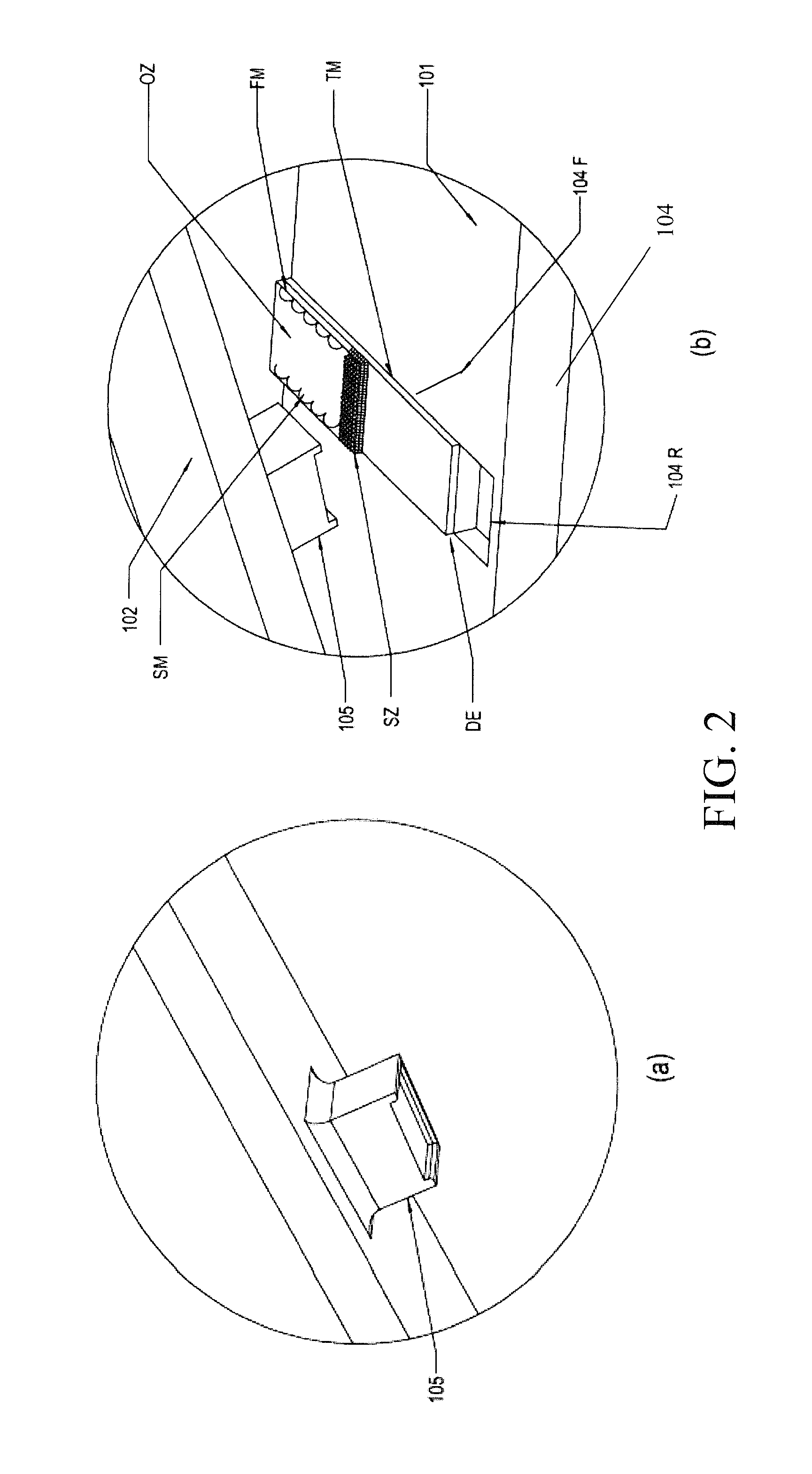
[0043]FIGS. 3a and 3b show a schematic representation of first embodiment of this disclosure. Accordingly, the filter module (104F) capable of retaining particles of interest module (104F) may be a single layer of lateral flow filter (see FIG. 3a) or it may be a multicomponent filter module (see FIG. 3b). The multicomponent filter Module includes a plurality of functional layers which enhance the performance of the device. The layers may include a sample matrix (SM), a filter matrix (FM) and a transport matrix (TM) stacked one over the other as shown as an example in FIG. 3b. An open zone (OZ1) and a sealing zone (SZ1) are provided in the filter matrix (FM). The transport matrix (TM) includes a proximal end (PE) and a distal end (DE). The plunger block (105) is configured to press the distal end (DE) of the transport matrix (TM) when a user operates the press rod (102) to move the plunger block (105) to press against the filter module (104F). An example of operation of the filter mo...

second embodiment

[0049]FIG. 5 shows a schematic representation of filter module (104F) of this disclosure. In the example shown, the plunger block (105) includes a proximal end (105P) and a distal end (105D) wherein a projection (105A) is provided at the proximal end (105P) and / or on the edges of the plunger block (105) for making pinching contact with the transport matrix (TM) so as to minimize back flow and side flow of filtered fluid sample (Fb) into the filter matrix (FM). The droplet of filtered fluid sample (Fb) may be collected in the reservoir (104R). Alternatively, the filtered fluid sample (Fb) may be collected by gravity flow into a cuvette (not shown in FIG. 5).

third embodiment

[0050]FIG. 6a-6c show a schematic representation of filter module (104F) of this disclosure. Accordingly, the filter module (104F) includes a filter matrix (FM), a transport matrix (TM) and a capillary reaction and / or reading zone (RZ). The sample matrix (SM) may also be provided as shown in FIG. 6(b). A buffer zone (BZ) is provided in-between the distal end of the Transport Matrix (TM) and the capillary reaction and / or reading zone (RZ). The capillary force of the reaction and / or reading zone (RZ) is more than the capillary force of the buffer zone (BZ) but less than that of the Transport Matrix (TM). The capillary force of the buffer zone (BZ) is less than the capillary force of the Transport Matrix (TM).

[0051]The reaction and / or reading zone (RZ) may be a cuvette with capillary space of 0.025 to 0.5 mm which may contain reactants and also act as the zone for optical reading of the reaction products for quantitative analysis.

[0052]The reaction and / or reading Zone (RZ) may also be...


PUM

PropertyMeasurementUnit
channel heightaaaaaaaaaa
capillary heightaaaaaaaaaa
capillary forceaaaaaaaaaa

Abstract

This disclosure provides a method and device for particle removal and droplet preparation for qualitative and quantitative bioanalysis. In one embodiment, the disclosed device includes a lateral flow filter through which the sample is filtered such that the filtrate fluid is collected in the distal end of the filter matrix. The filtered fluid is made to eject from the matrix to form a droplet by pressing/squeezing the distal end of the filter only, with the help of a suitably shaped plunger means.

Description

TECHNICAL FIELD[0001]This disclosure relates generally to devices and methods for removing particles from fluids and making droplets of filtered fluid in free form as pure liquid without any filter matrix for qualitative and quantitative bioanalysis, and more particularly to, a device for separating RBCs from blood and preparing a droplet of blood plasma for Point of Care applications.BACKGROUND ART[0002]Analysis of analytes in various biological fluids is of great interest for the diagnosis of diseases and disorders. Generally, the presence of particulates and cellular matter in the fluids interfere with the assay procedures. For example, when analyzing for analytes in blood, the removal of Red Blood Cells (RBC) is often necessary to get meaningful results.[0003]Conventional methods such as centrifugation, sedimentation, etc can be readily used to separate RBCs. However, the conventional methods suffer from the disadvantage that they require separate equipment and technician time f...

Claims


Application Information

Patent Timeline
Patent Type & Authority Applications(United States)
IPC IPC(8): G01N33/49
CPCB01L3/0268B01L3/0272B01L3/5023B01L2300/0681G01N2001/4083B01L2400/0406B01L2400/0481G01N1/4077B01L2300/0825G01N33/491
Inventor GUPTA, NALINI KANT
Owner ADVANCED MICRODEVICES PVT
Why Eureka
Try Eureka