Electroregeneration apparatus and water treatment method

a technology of electrochemical devices and water treatment methods, applied in the direction of liquid/fluent solid measurement, fluid pressure measurement, peptides, etc., can solve the problems of inability to process intermittent flows, edi systems currently have limitations that prevent the use of typical wells and public water sources, and the capacity of resins are not optimized for capacity, so as to improve the current electrochemical device design and reduce the voltage required

Active Publication Date: 2011-02-24
TANGENT COMPANY
View PDF74 Cites 15 Cited by
  • Summary
  • Abstract
  • Description
  • Claims
  • Application Information

AI Technical Summary

Benefits of technology

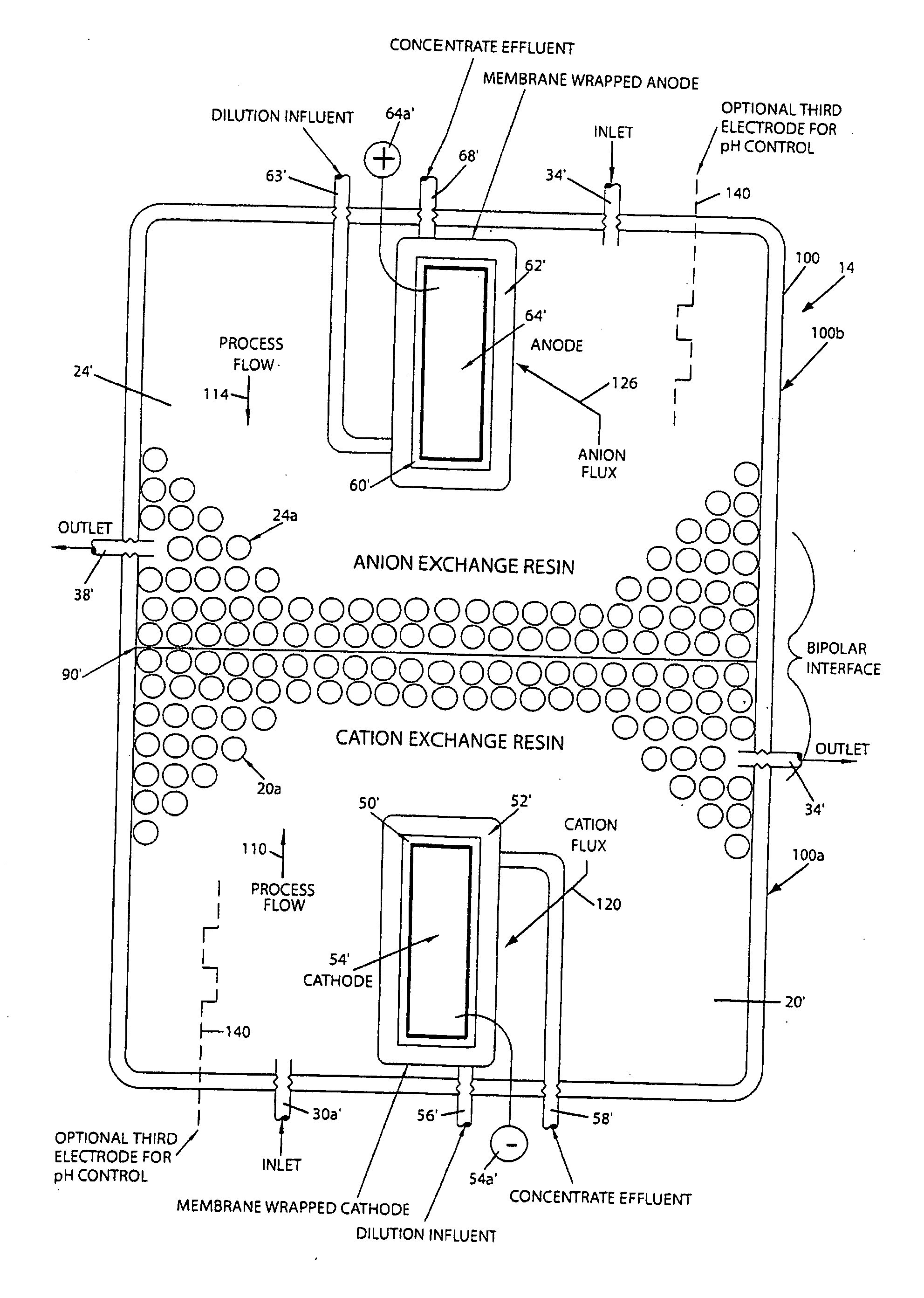
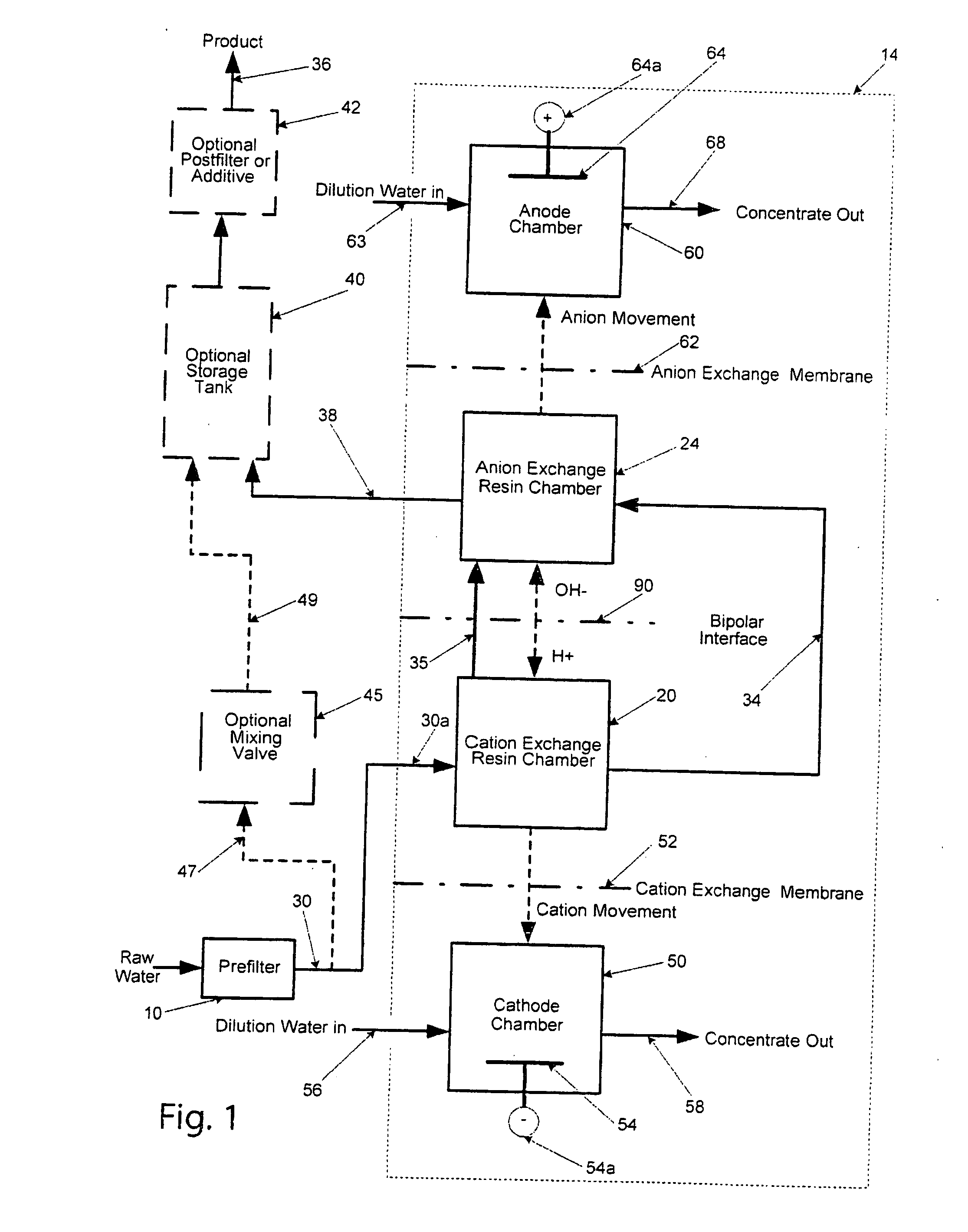
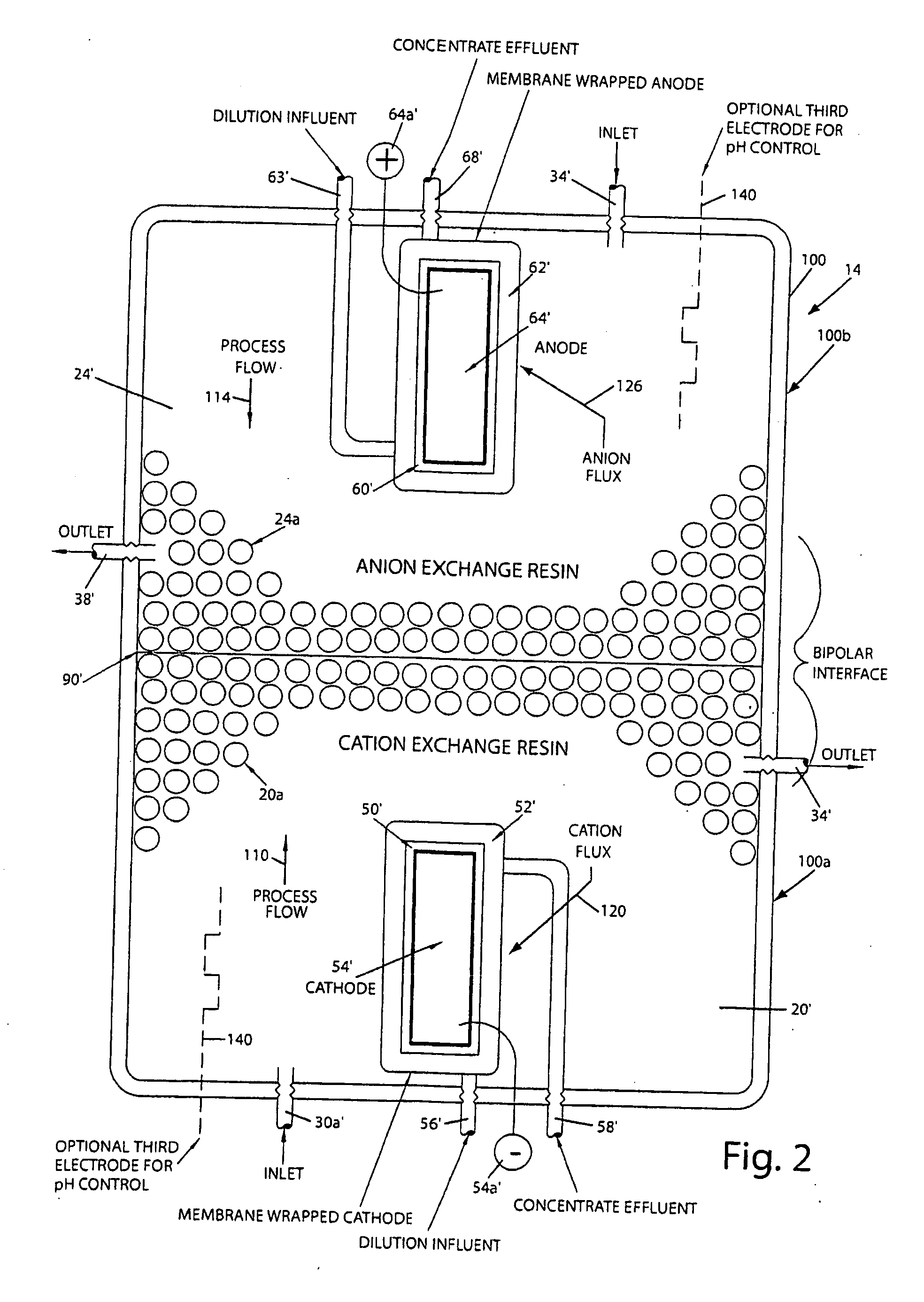
[0011]The present invention provides a new and improved water treatment apparatus and method that utilizes electricity to regenerate the cation and anion exchange resin chambers while maintaining a relative scale free environment. It also improves on the current electrochemical device designs by lowering the voltage required, eliminating the requirement of continuous electricity during product water flow and also eliminating the requirement of product water flow when electric potential for the regeneration of the resin chambers is applied.

Problems solved by technology

Therefore resins are not optimized for capacity but for other properties that influence transport, such as water retention and selectivity.
Many other commercial EDI systems currently have limitations that prevent the use on typical well and public water sources.
Such limitations may include the requirement for softening or reverse osmosis pretreatment methods to prevent scaling that would lead to a device failure, inability to process intermittent flows, and very limited ion exchange reserve capacity.
If there is no product water flow then the device cannot regenerate itself as designed.
Other similar devices are designed for high purity water production and cannot treat water with high concentrations of ions, making them impractical for normal household use.

Method used


Image

  • Electroregeneration apparatus and water treatment method
  • Electroregeneration apparatus and water treatment method
  • Electroregeneration apparatus and water treatment method

Examples


example i

[0061]The effectiveness of an electroregeneration ion removing cell of the present invention was evaluated using a test cell at a scale of 1:200 of the desired size. Results of the test are presented in Table 1.

TABLE 1Inlet Water Source: Cell configurationTime10.0010.1513.3015.3516.307.458.15Amperage35353535353535(mA)Voltage (V)V0-V16.16.085.955.835.766.156.14post anionConductivity138.265.716.79.46.915.818.4resin(μS / cm)PH9.18.848.18.188.484.514.42T (° C.)21.721.921.521.922.218.1post cathodeConductivity10601068106712981310chamber(μS / cm)PH32.982.962.812.87T (° C.)22.22222.518.618.9Flow RatesProduct2.62.62.62.62.62.6(ml / min)Hard Water (300-320 mg / L) of hardness as Calcium Carbonate)upflow thru cation resin, then up thru anion resin, bipolar membrane

[0062]As seen in Table 1, a relative low voltage drop of 6 volts was maintained while producing water in the desired range of conductivity and the waste water leaving the cathode chamber is indicative of the ions moving in the manner as show...

example ii

[0079]

TABLE 302 / 26-02 / 25-02 / 26-02 / 27-02 / 2802 / 2702 / 27-02 / 2702 / 27-02 / 28Feed02 / 26 Waste02 / 27 WasteWasteProductProductProductAnalysisWaterCompositeCompositeCompositeCompositeCompositeCompositepH7.227.077.497.919.369.349.45Conductivity6223,0832,1701,724455254μS / cmChloride32.8127.4200.9181.3mg / L as ClSulfate mg / L451,288650365as SO4Sodium12675370185111213mg / L as NaPotassium291081mg / L as KCalcium83.2564.574.0122.0mg / L as CaMagnesium21.529.079.068.0mg / L as MgTotal295.4279.5508.2582.6Hardnessmg / L asCaCO3Silicon mg / L6.73.510.219.61.7as SiIronmg / L as Fep-Alkalinity0.00.00.00.04.04.04.0mg / L asCaCO3m-Alkalinity247.480.0284.0404.024.030.032.0mg / L asCaCO3

[0080]The effectiveness of an electroregeneration ion removing cell constructed in accordance with FIG. 6, was evaluated using a test cell. The results of the test are presented in Table 3. From Table 3, it can be seen that during the four day test (Feb. 25, 2008-Feb. 28, 2008), the hardness of the incoming water was reduced from 295.4 mg / L as CaCO...


PUM

PropertyMeasurementUnit
voltageaaaaaaaaaa
thickaaaaaaaaaa
thickaaaaaaaaaa

Abstract

A water treatment apparatus that includes a cation exchange chamber containing a cation exchange resin and an anion exchange chamber containing an anion exchange resin. A bipolar interface is located between the resin chambers and defines a zone of water disassociation. A cathode communicates with the cation exchange chamber through a cation exchange membrane. An anode communicates with the anion exchange chamber through an anion exchange membrane. Dilution or flushing water flows through cathode and anode chambers and conveys captured ions to a drain or other waste connection. A baffle may be used in some configurations to divide a resin chamber into an exhausted resin region and a regenerated resin region and causes incoming water to flow through the exhausted resin region first. The exhausted resin region is located near its associated electrode, thus improving the electrical efficiency of the cell. In an alternate design, the apparatus includes a cathode/anode chamber, an anode chamber and an auxiliary electrode chamber disposed between the cathode/anode chamber and a cation exchange media chamber. An anion exchange membrane separates the cathode/anode chamber from the auxiliary electrode chamber. The anode chamber, cathode/anode chamber and auxiliary electrode chamber are energized in predetermined sequences to create both service cycles which produce softened water with reduced ionic content and cleaning cycles to de-scale the auxiliary electrode chamber and/or anion exchange membrane located between the cathode/anode chamber and the auxiliary electrode chamber.

Description

FIELD OF THE INVENTION[0001]The present invention relates generally to water treatment processes and in particular to a method and apparatus for removing cations and anions from water using ion exchange resins and membranes and using electricity to regenerate the resins.BACKGROUND ART[0002]There are many methods and apparatus disclosed in the prior art for removing minerals from water. A water softening apparatus such as that disclosed in U.S. Pat. No. 3,891,552 is an example of a water treatment system that is used to remove certain “hard” ions in order to produce softened water. When substantially all of the ion sites in the water softening resin hold a “hard” ion, the resin must be regenerated. In a typical water softener of the “ion exchange” type, a resin tank containing a water softening resin is utilized. In particular, the “hard” water is passed through the resin tank where the water exchanges its “hard” ions of calcium, magnesium, etc. for “soft” sodium or potassium ions lo...

Claims


Application Information

Patent Timeline
Patent Type & Authority Applications(United States)
IPC IPC(8): C02F1/469B01D61/44B01J41/00B01J39/00
CPCB01D61/48B01D61/485C02F1/4695B01D2313/345B01D2311/18
Inventor RATH, DAVID F.HANSEN, CHRISTOPHER L.KIRMAN, LYLE EDWARDPUTKA, CHRISTOPHER S.BOLTON, JAMES E.
Owner TANGENT COMPANY
Why Eureka
Try Eureka